4.
INTERCOM DC INPUT POWER CIRCUIT.
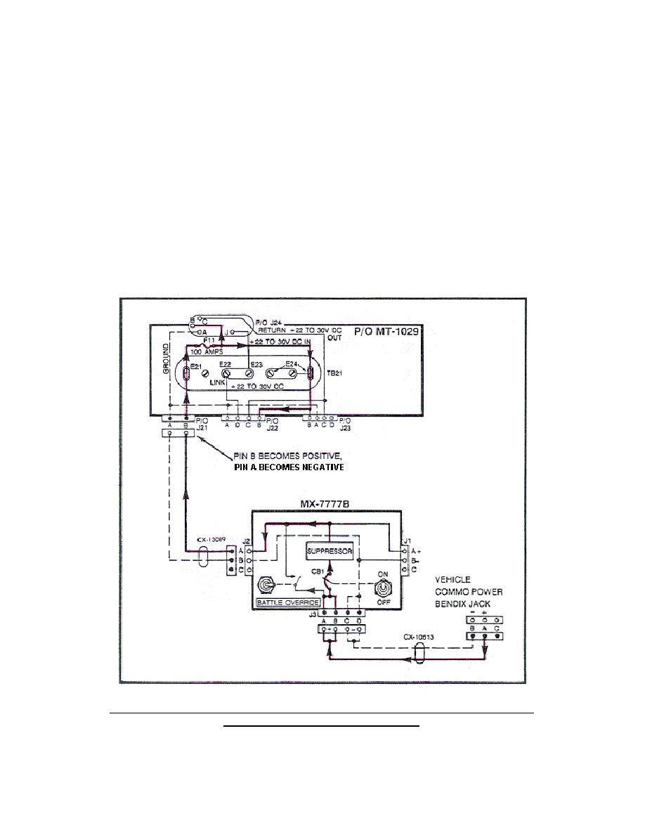
a. The DC input power circuit provides source voltage, 22-30 volts DC
from the vehicle electrical system (Figure 1).
Starting at the vehicle
communication power Bendix jack, 22-30 volts DC is applied to power cable
CX-10613, pin A (positive) and pin B (negative); through the CX-10613l cable
to the MX-7777B suppressor jack 33, pins A and B (positive) and pins C and D
(negative). The MX-7777B suppressor protects the system from voltage surges
and from system overloads and provides main power ON/OFF control. Voltage
is provided through the MX-7777B to jack J2, pin A (positive) and pin B
(negative). From the MX-7777B J2, voltage is provided through the CX-13089
power cable to J21 on the MT-1029 mount, pin A (negative) and pin B
(positive).
In the NT-1029, pin A of J21 is wired directly to pins A of
J22, J23, and J24 providing these jacks with a common ground connection.
The positive 22-30 volts DC is applied from pin B of J21 to pins B of J22,
J23 and J24. (Trace these circuits on the system diagram provided at end of
subcourse.)
Figure 1.
DC source voltage from vehicle communication power
Bendix jack through MT-1029.
4


 Previous Page
