nitrogen gas. This pressurization allows the waveguide to handle more power with less chance of
arc-over and also prevents the collection of moisture or condensation in the waveguide. Cooling
systems are used to remove heat from waveguides that handle high power.
(2) The choke joint operates like an RF choke in a power supply. An RF choke keeps RF energy in
the circuit where it belongs, and the choke joint keeps the electromagnetic energy in the
waveguide where it belongs. The energy loss in a good choke joint is less than 0.03-db and the
loss in a well-machined, unsoldered joint is less than 0.05-db.
2-14.
CIRCULAR WAVEGUIDE
For mechanical reasons, a rotating joint must be circular and requires a coaxial line or a section of circular
waveguide.
a. Transverse electric (TE) and transverse
magnetic (TM) waves are propagated in circular
waveguides in almost the same manner as in
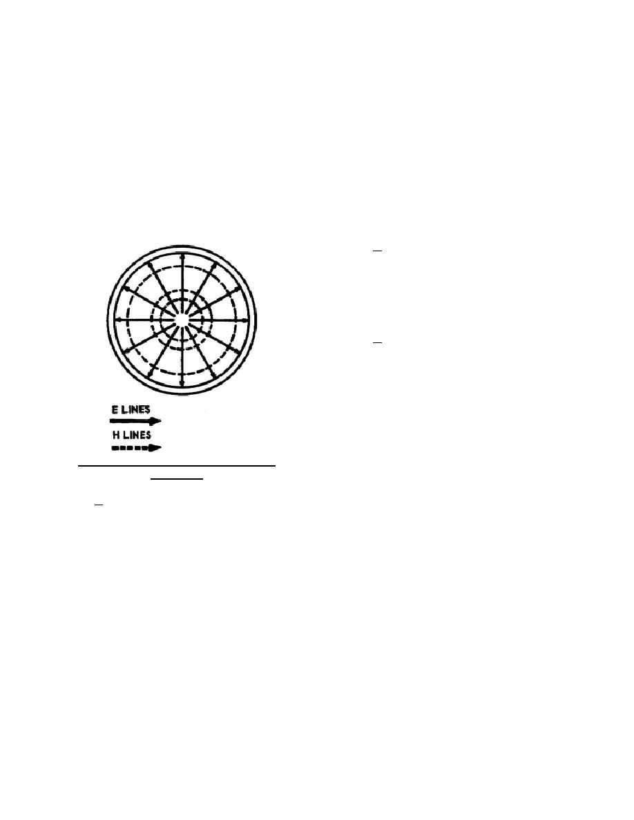
rectangular waveguides. The field configuration in
the circular waveguide closely follows a sine wave
pattern (fig. 65).
b. The boundary conditions used in the
rectangular waveguide also apply to the circular
waveguide. Under these conditions the electric field
must be perpendicular to the surface of the
conductor, and the magnetic field parallel to the
surface of the conductor. When these boundary
conditions are fulfilled in the circular waveguide, the
electric field exists between the center of the
waveguide and the wall, and the magnetic field
exists around the inside of the waveguide as shown
Figure 82. Field configuration in a circular
in figure 82.
waveguide.
c. The dominant mode in the circular waveguide is similar to the dominant mode in the rectangular
waveguide. In the TE mode, the electric field is perpendicular to the direction of propagation. In the TM mode,
the magnetic field is perpendicular to the direction of propagation. The TE mode in figure 83 shows that the
electric lines are circular around the center of the waveguide and perpendicular to the direction of propagation. In
the TM mode, the magnetic lines are circular around the center of the waveguide and perpendicular to the
direction of propagation.
344 L2
80


 Previous Page
