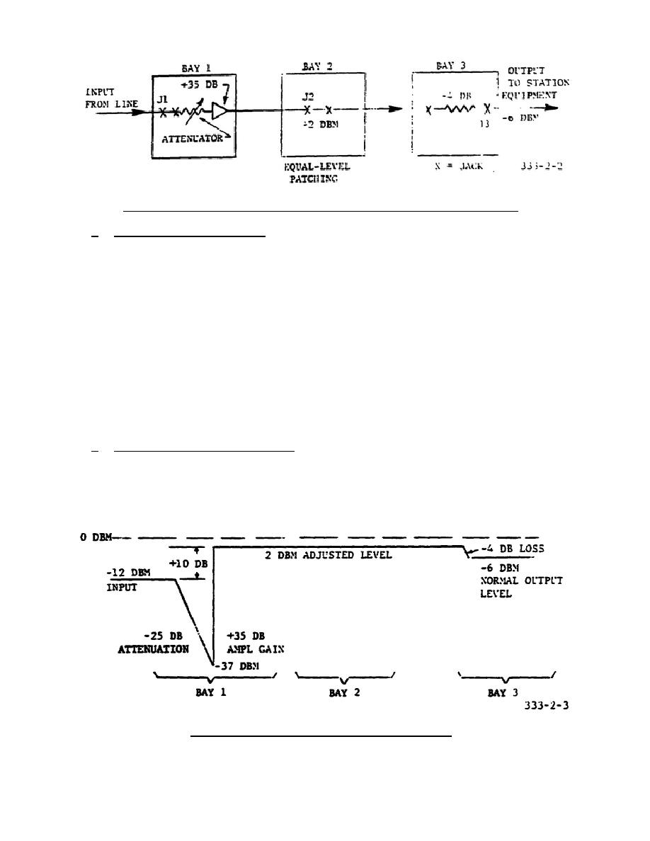
Figure 2-2.
Three-bay lineup in a technical control center.
b. Circuit Specifications.
The planned levels in the circuit are as
follows:
(1) Expected (normal) level of input signal at bay 1 measures -12 dbm.
(2) The level at bay 2 is adjusted to -2 dbm.
The overall gain of the
attenuator-amplifier combination is therefore 10 db (difference between
-12 dbm and -2 dbm). The level of every circuit passing through bay 2
is adjusted to the same level (-2 dbm) to make possible equal-level
patching.
(3) A 4-db pad in bay 3 drops the level to -6 dbm for the equipment which
the line circuit serves. This output level will always be maintained
so long as the level is correctly adjusted by the attenuator in bay 1.
The attenuator is therefore the only variable that need be adjusted in
this line circuit.
c. Transmission Level Diagram.
A transmission level diagram shows the
changes in level which the signal undergoes as it passes through a circuit.
Horizontal lines show levels, while vertical lines indicate amplifier gains.
Slanting lines indicate losses. The transmission level diagram of the three-
bay lineup in figure 2-2 is shown in figure 2-3.
A horizontal line
representing 0 dbm (1 mw) is always used as reference.
Figure 2-3.
Transmission level diagram.
18


 Previous Page
