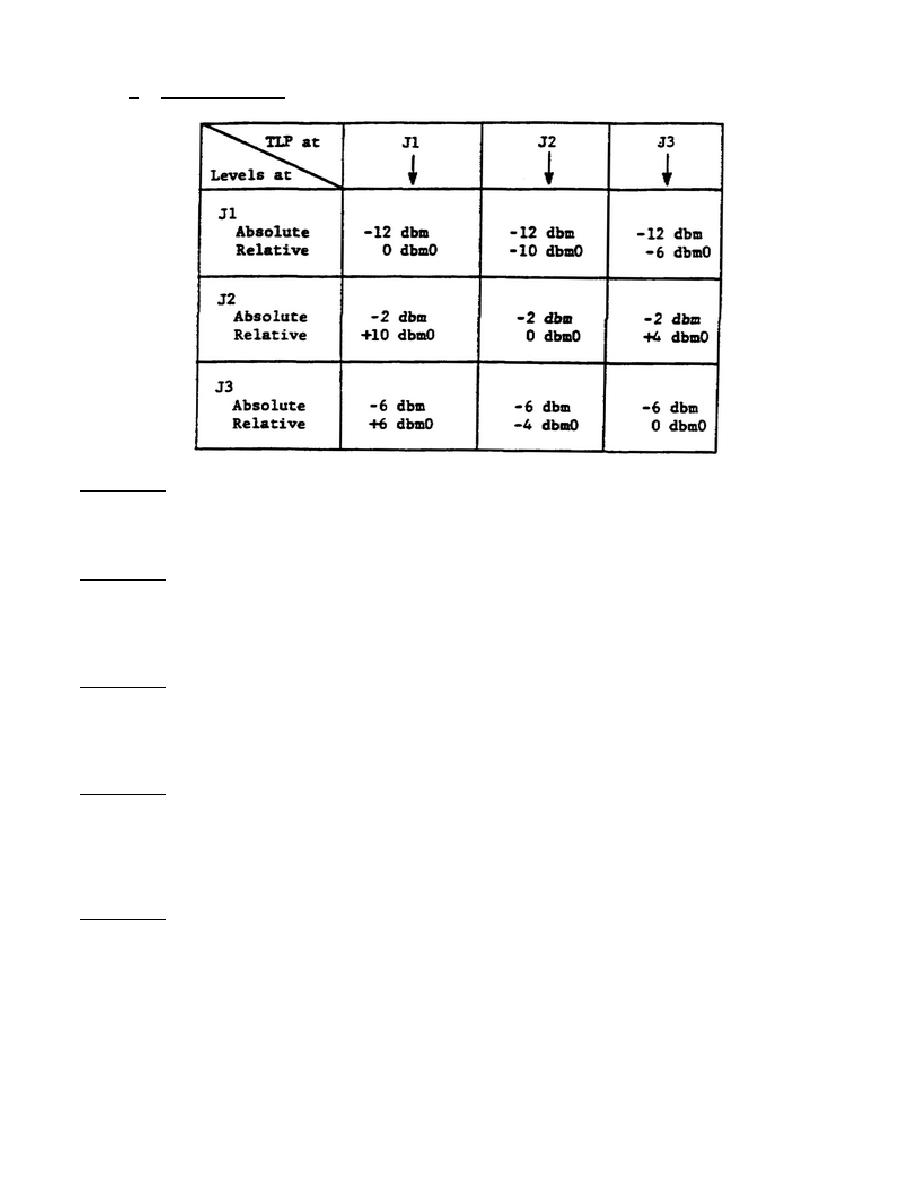
f. Using the TLP.
Example 1: The TLP at jack J1 is taken as zero (0 dbm0).
Reading downward
under J1 it is evident that the relative level at J2 is +10 dbm0,
and at J3 it is +6 dbm0. The actual levels at jacks J2 and J3 will
therefore be -2 dbm and -6 dbm, respectively.
Example 2: Assume that the level is -2 dbm at TLP (J2) in bay 2.
What are the actual levels at jacks J1 and J3?
The relative levels at J1 and J3 will be -10 dbm0 and -4 dbm0,
respectively. The actual levels at J1 and J3 will be -12 dbm and -6
dbm, respectively.
Example 3: Assume that the level is -6 dbm at TLP (J3) in bay 3.
What are the actual levels at jacks J1 and J2?
The relative levels at J1 and J2 will be -6 dbm0 and 44 dbm0,
respectively. The actual levels at J1 and J2 will be -12 dbm and -2
dbm.
Example 4: Assume that the TLP is at jack J1 with normal level of -12 dbm.
Since this is the TLP, the two values are related: -12 dbm = 0 dbm0.
Now suppose the input signal drops to a level of -18 dbm. What is
the relative level?
The level of -18 dbm is 6 db below the reference level at TLP, and
is therefore quoted as -6 dbm0.
Example 5: Assume that the TLP is at J2 with normal signal level of -2 dbm.
Assume further, that the maximum relative noise at this point in the
circuit is established at -40 dbm0. What is the actual noise level?
40 db below -2 dbm is -42 dbm. That is the actual noise level.
20


 Previous Page
