(1) Normal input level is -12 dbm which the attenuator drops to -37 dbm,
a loss of 25 db. The 35-db fixed-gain amplifier raises the level of
-37 dbm to the required -2 dbm adjusted level. The overall gain of
the attenuator-amplifier combination is therefore the difference
between -12 dbm and -2 dbm, an overall gain of 10 db.
(2) The signal level of -2 dbm remains without change through the jack
circuits of bay 2. In other words, there is neither gain nor loss
in bay 2. Another way to say this is that the gain is 0 db and the
loss is likewise 0 db.
(3) A 4-db pad in bay 3 drops the signal level to -6 dbm, the level
required by the equipment.
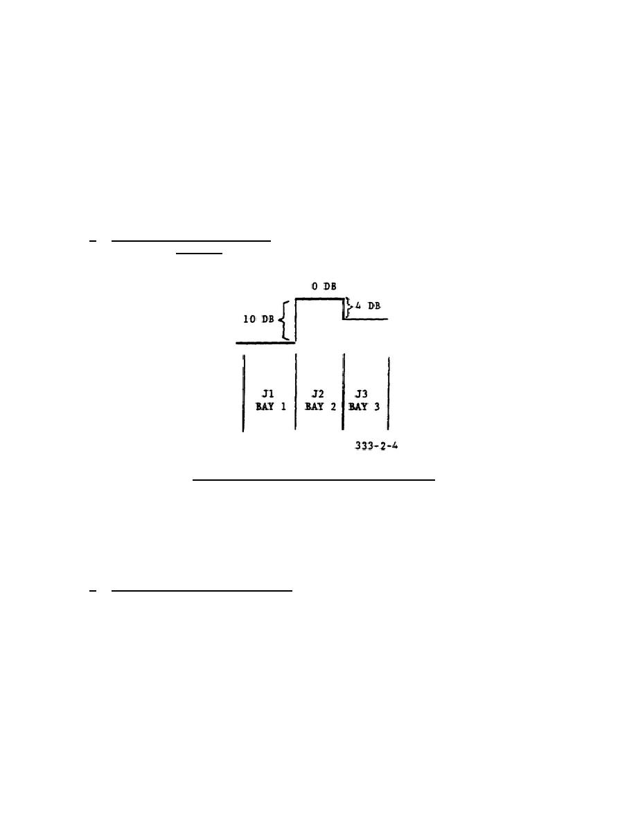
d. Loss-Gain Characteristic. A loss-gain characteristic is a graph that
depicts only the changes in level without reference to levels.
Figure 2-4
shows the characteristic of the three-bay layout in figure 2-2.
Figure 2-4.
Loss-gain characteristic.
(1) The overall gain of the attenuator-amplifier combination in bay 1 is
10 db.
(2) There is neither gain nor loss in bay 2.
(3) The loss in bay 3 is 4 db.
e. Transmission
Level
Point.
The
advantage
of
the
loss-gain
characteristic is that it permits a prediction of circuit performance without
resort to levels. Thus if one level is given at any point in the system, all
other levels can be determined from it. The point selected becomes the TLP, to
which all losses and gains in the system are thereafter referred. The TLP is
assigned the reference level of 0 dbm0, and all other points in the system are
identified as being either positive (gain) or negative (loss) with respect to
the level at the TLP. Again, referring to the three-bay lineup shown in figure
2-2, we will derive the loss-gain characteristics of three different TLP
designations. Assume that the actual (absolute) input level at jack J1 in bay
1 is -12 dbm.
19


 Previous Page
