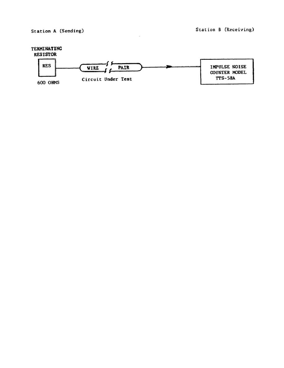
Figure 1-3.
Impulse noise test, block diagram.
b. Recording of test data. Readings obtained in the test are recorded
in the impulse noise data sheet, figure 1-4. Note the space for recording
of time at starting and ending of the test.
The DCA parameter
identification is entered in DCS Circuit Type.
6


 Previous Page
