ATTACHED MEMORANDUM
1-1. Idle Circuit Noise Test.
The idle circuit noise test measures the
total noise on a line from which the signal has been removed and the line
terminated in a matching resistor. Any level reading thereby represents the
noise on the circuit.
The total noise includes impulse and random noise,
together with harmonic distortion, crosstalk, and intermodulation products.
Impulse and random noises are generally developed along the line (or radio
transmission path), while the remainder of the total noise, called white
noise, is developed within equipment items such as channels of telephone
carrier terminals, line amplifiers, and radio transmitters and receivers.
White noise is usually measured on an RMS voltmeter because of its
relatively constant value.
Impulse noise, on the other hand, is handled
differently because of the short-term duration of noise peaks, sometimes too
short to register on a noise-measuring set.
Harmonic distortion is also
measured as a separate quantity.
The idle channel noise test produces a
figure that is the lowest level of all noise encountered in a working system
when that system is correctly prepared for the idle noise test with all
signals removed.
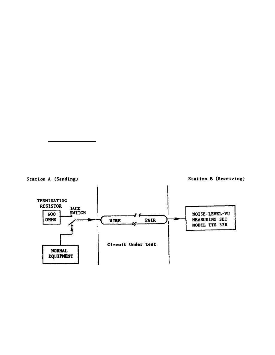
a. Test arrangement. A block diagram of a typical test arrangement for
idle circuit noise is shown in figure 1-1.
Test equipment includes a
terminating resistor at one end of the line and Noise-Level-VU Measuring Set
Model TTS-37B at the other end. The TTS-37B shown in figure 3 of appendix
A, section IV, is designed to measure RMS values of the total noise. Tests
are made in each direction of transmission (A to B, then B to A).
Figure 1-1.
Idle circuit noise test, block diagram.
2


 Previous Page
