buncher, a drift tube through which the velocity-
modulated beam travels, and a unit called a catcher.
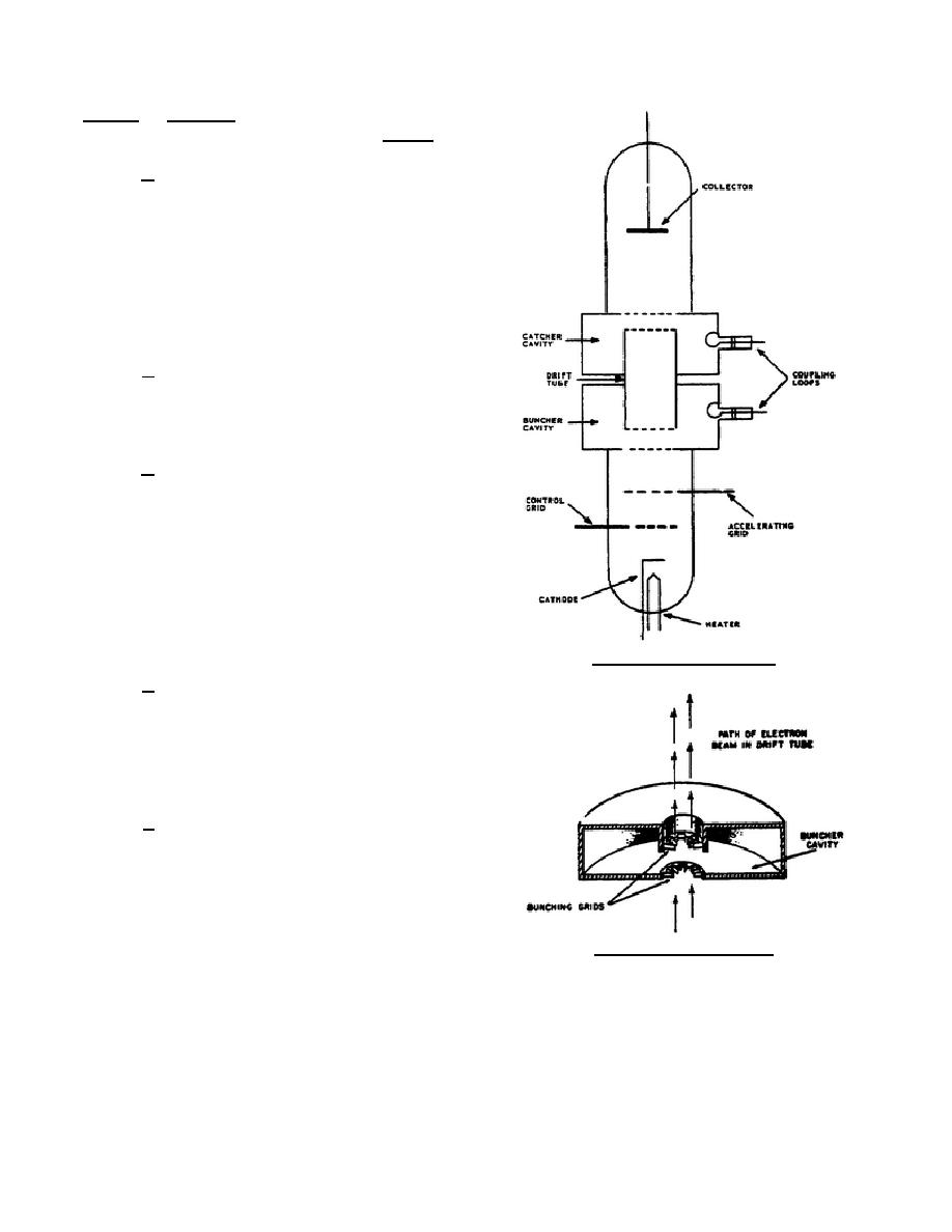
b. The klystron beam source, shown in
figure 3, consists of the heater, cathode, control grid,
and accelerating grid. The control grid controls only
the number of electrons in the beam. No signal is
applied to it to cause the flow of electrons to vary.
The accelerating grid speeds up the electrons that are
passed by the control grid. The velocity of the
electrons passing through the accelerating grid can
be changed by varying the accelerator grid voltage.
c. The buncher is the resonant cavity and is
usually called the buncher cavity. This is a reentrant
type cavity and has grids in the cavity, as shown in
figure 4.
d. If microwave energy is coupled into the
cavity by the coupling loop, oscillations are set up
and an alternating voltage appears between the
bunching grids. When the second grid is more
positive than the first grid, electrons passing through
the buncher grids are speeded up, or accelerated.
When the second grid is more negative than the first
grid, electrons passing through the buncher grids are
slowed down. The electron beam is now velocity
modulated as it passes through the buncher grids.
Figure 3. Simple klystron.
e. The buncher cavity is a reentrant-type
cavity in order to reduce the spacing between the
buncher grids. The electron velocity is usually high
so that the time required for an electron to pass
between the buncher grids is only a small fraction of
a cycle.
f. The drift tube is an evacuated tube and
provides a path for the velocity-modulated electron
beam. The drift tube is between the buncher and
catcher cavities, as shown in figure 3. The catcher
cavity and the buncher cavity are identical in size
and shape but their functions are different.
Figure 4. Buncher cavity.
344 L1
5


 Previous Page
