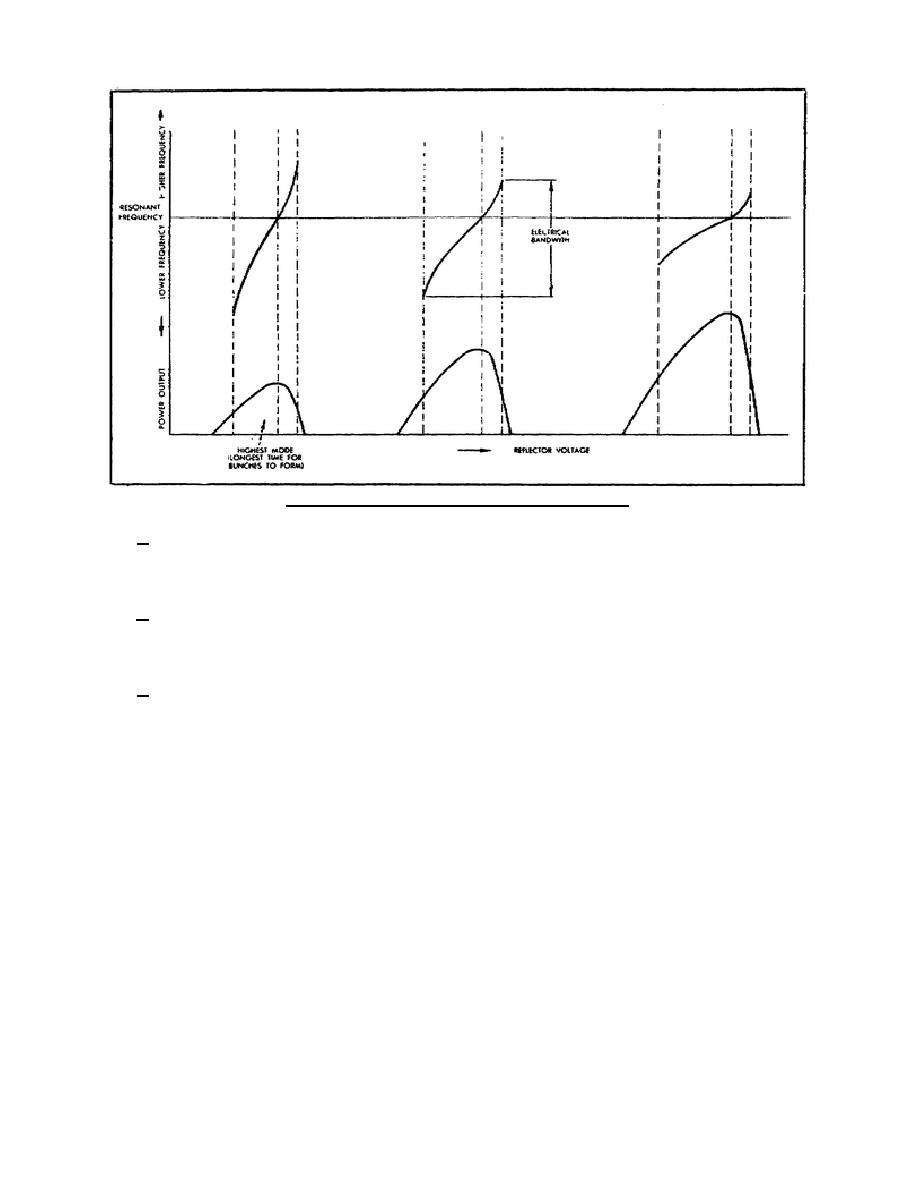
Figure 8. Klystron modes and electrical bandwidth.
c. If the repeller plate voltage is changed to be less negative (in the same mode), the reactance
introduced is inductive. The frequency of oscillations will now be lower than the resonant frequency of the
cavity.
d. Broader tuning ranges are available in the higher modes, but the power output is decreased
considerably. This influences the desired mode of operation because the most powerful mode has the narrowest
tuning range.
e. Klystrons are also tuned mechanically over much wider ranges than is possible with electrical tuning.
Figure 9 shows a reflex klystron commonly used in microwave equipment. The resonant cavity is small and
shaped like a doughnut. The upper shoulder of the metal tube envelope is part of the cavity wall and is made
flexible. When pressure is applied to the top of the tube by means of the tuning strut, the upper cavity grid is
moved closer to the lower cavity grid and the capacitance between the grids increases. This decreases the
resonant frequency of the cavity. The electrical tuning range is greatest near the center of the mechanical tuning
range. Mechanical tuning is used as a coarse frequency adjustment, and electrical tuning is used as a fine
frequency adjustment. Tuning slugs, tuning paddles, and plungers are also available as mechanical tuning devices
for klystrons.
Section IV. MULTICAVITY POWER-AMPLIFIER KLYSTRON
1-10.
INTRODUCTION
Electron transit time makes operation of the klystron possible. To take advantage of transit time effects, the
klystron must be made relatively large. The larger klystrons, with more than two resonant cavities, develop much
higher gain and operate with greater efficiency.
344 L1
10


 Previous Page
