1-12.
COMPONENT DIMENSIONS AND PLACEMENT
a. The grids are eliminated in the resonant cavities in the multicavity klystron because of the high
electron velocities. The edges of the cavity gaps are flush with the drift tube wall to avoid interrupting electrons
in the beam. The cavity gap spacing is determined by the electron transit time between gaps and the amplitude of
the RF voltage (cavity signal) across the gap. The ideal condition is zero transit time, but this is not possible. A
cavity gap that produces a transit time of one-quarter cycle is usually satisfactory.
b. If the gap spacing is very small to reduce transit time, the cavity impedance is lowered, and this is the
same as increasing the capacitance of a tuned parallel resonant circuit. In the high-power multicavity klystron, the
reduction of gap spacing will allow the high RF voltage to arc over and the klystron will fail to operate.
c. The diameter of the drift tube determines the degree of coupling between the cavities and the electron
beam, and affects the complexity of the arrangement for focusing the electron beam. The smaller diameter
provides a higher degree of coupling, but it complicates the focusing. The limiting condition of the drift tube
diameter is that the diameter of the tube must be approximately one-half the wavelength of the operating
frequency. This is necessary to avoid standing waves along the drift tube. The drift tube diameter should permit
satisfactory beam coupling and practical focusing.
1-13.
BUNCHING
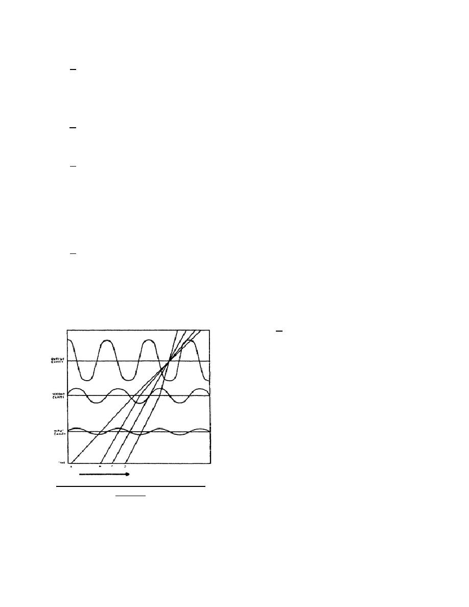
a. The output of any klystron is developed by velocity modulation which produces bunching. The
multicavity klystron uses higher electron velocities than the two-cavity klystron, so more velocity changes by RF
voltages are required for bunching. The electrons that leave the cathode are influenced only by the voltage
between the cathode and drift tube. As the electrons pass through the input cavity, velocity modulation takes
place. As electrons reach the second cavity, enough bunching has occurred to excite the second cavity, causing it
to oscillate. The cavity signal across the second cavity causes additional velocity modulation so that bunching
will occur at the output cavity.
b. In figure 14, the electrons at time A
experience a uniform deceleration from the input
and second cavities. The electrons at time B
experience acceleration from the input cavity and
then are decelerated by the second cavity signal so
that they will arrive at the output cavity at the same
time as the time A electrons. Electrons at time C
have no cavity fields acting on them. Electrons at
time D are decelerated by the input cavity signal but
are accelerated by the second cavity signal. The
result is bunching at the output cavity in one cycle of
the input signal.
Figure 14. Bunching action in a multicavity
klystron.
344 L1
14


 Previous Page
