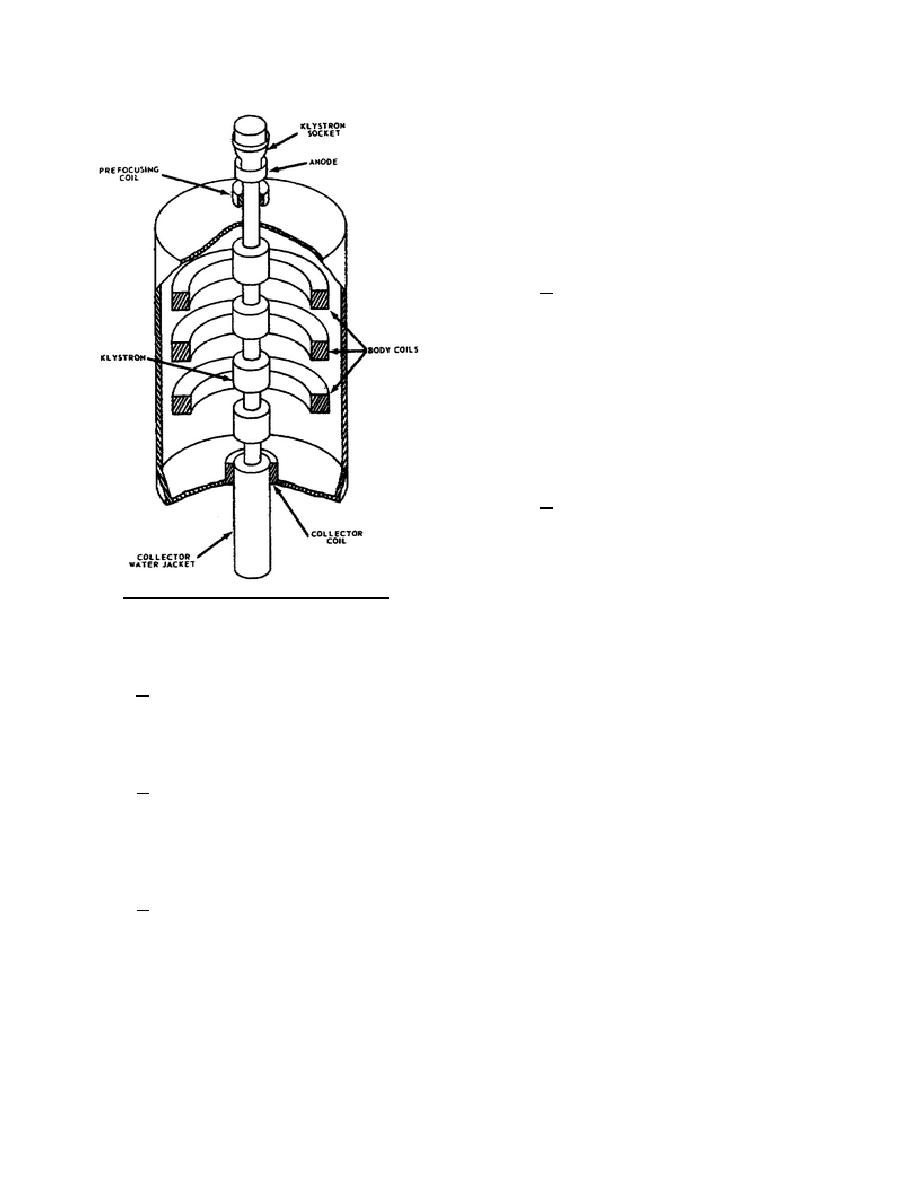
and be wasted. The electrons that do strike the drift
tube wall become body current. Body current is
passed through an external circuit, back to the
positive terminal of the beam power supply, as
shown in figure 15. This current is read on the meter
labeled BODY CURRENT. By adjustment of the
individual coil currents, body current is kept to a
minimum.
d. The collector coil is located in the
bottom of the magnetic frame which supports the
mounting flange of the klystron. The mounting
flange, being of magnetic material, serves to
establish the magnetic field needed near the end of
the drift tube. The collector coil current is adjusted
in the same manner as the body coil current so as to
reduce the body current.
1-20.
KLYSTRON TUNING
a. Klystrons with as many as six cavities
have been developed to permit broadband tuning.
The conventional tuning methods are stagger tuning
and cavity loading. No rules can be given to account
for all the methods and variations in the various
Figure 16. Klystron and magnetic coils.
broadband tuning systems. Each system is a
separate tuning problem, and the klystron can be correctly tuned only by careful observance of the instructions
that accompany it into the field.
b. In general, three-cavity klystrons will provide bandwidths of approximately 0.3 percent of their
operating frequency when they are correctly tuned and their driving power is suitably increased. Four-cavity
klystrons can provide bandwidths of about 0.6 percent of their operating frequency when they are correctly
stagger tuned, and with increased driving power.
c. Cavity loading in combination with stagger tuning will give increased bandwidths up to 2.0 percent of
the operating frequency when used with klystrons of five and six cavities. However, loading materially
diminishes the gain of the klystron and results in reduced efficiency and power output.
1-21.
HEAT EXCHANGER
a. The purpose of the heat exchanger is to cool and circulate the liquid that removes the heat from the
klystron. The operation of the heat exchanger shown in figure 17 is similar to the operation of the cooling system
of an automobile. Assume that the coolant is of normal room temperature when the unit is started. The coolant
will bypass the heat transfer coils because the thermostatic bypass valve will be closed, thus closing
off that portion of the line which goes to that area.
As the heat from the drift tube heats
344 L1
18


 Previous Page
