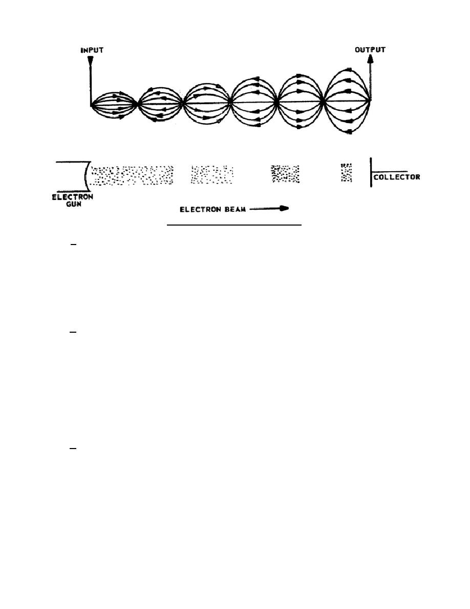
Figure 20. Simple traveling-wave tube.
f. This simplified traveling-wave tube will not work because the RF signal travels at the speed of light
and the electron beam cannot be accelerated beyond this velocity. For this reason the TWT is designed with a
slow wave structure that will delay the RF signal so that the electron beam can be accelerated to a higher speed
than that of the RF signal. The transmission line used to delay the RF signal is a helix (coil of wire). The helix (a
nonresonant line) delays the axial velocity of the RF signal to where it is only one-tenth of the axial velocity in the
straight-wire line. Now the axial velocity of the electron beam can be controlled so that it is equal to or greater
than the axial velocity of the RF signal. The helical-type delay line permits a greater concentration of the RF field
parallel with the axis of the helix and causes better velocity modulation of the electron beam.
g. In figure 21, if an electron beam is directed through the center of the helix and an RF signal is
applied to the RF input, the traveling-wavetube will amplify the input signal. (Bear in mind that the focusing
magnet, not shown here, is a vital part of the TWT.) The RF signal is coupled to the helix through the transformer
coupling and causes bunching to occur, as shown by the wave shape in figure 21. Amplification of the RF signal
on the helix begins as the field formed by the bunches interacts with the field from the RF signal. Each newly
formed electron bunch adds a small amount of energy to the RF signal on the helix. The slightly amplified RF
signal then causes a denser electron bunch, which, in turn, adds still more energy to the RF signal. This process is
continuous as the RF signal and the bunches progress along the helix. Notice how amplification of the RF signal
increases as the electron bunches get more in phase with the negative field of the RF signal. This is when
maximum deceleration occurs and the electron beam gives up maximum energy to the helix. This energy then is
coupled from the helix to the output coupler of the tube.
h. The attenuator placed near the center of the helix reduces or attenuates the RF signal on the helix so
that the signal from the output side cannot
344 L1
22


 Previous Page
