1-28.
O-TYPE BACKWARD-WAVE OSCILLATOR
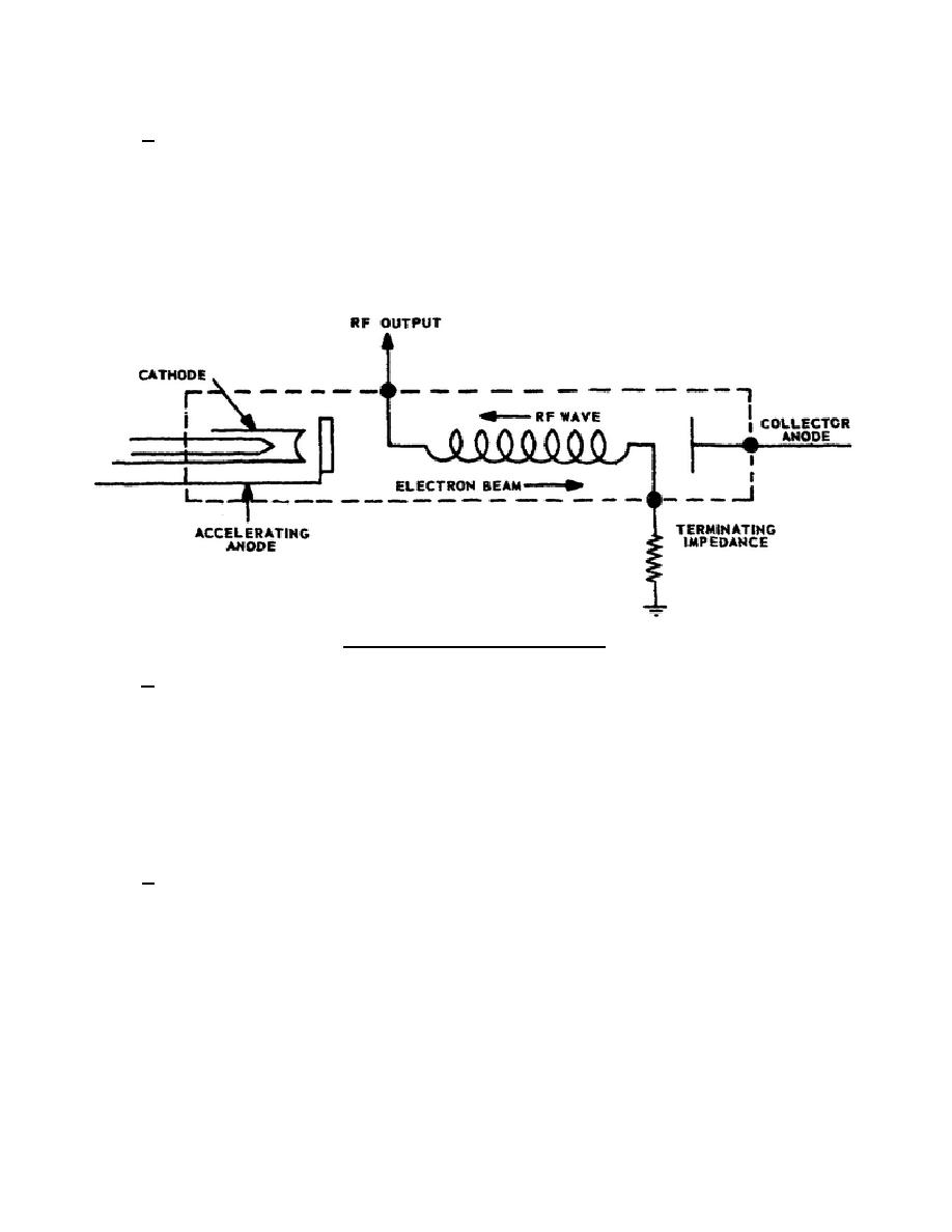
a. In figure 23, as the electrons leave the electron gun and are accelerated toward the collector anode,
they generate noise by shot and thermal effects. The noise signal is random in frequency, and almost all
frequencies from 0-109 hertz are present. Each of these frequencies tends to develop a wave traveling on the
helix. This wave travels back toward the electron gun end of the tube. If the electron beam has a slightly higher
velocity than the velocity of the signal on the helix, there will be interaction between the electron beam and the
signal on the helix, causing the electron beam to give up energy to the signal on the helix. The signal on the helix
will increase in amplitude as it approaches the gun end of the tube. This amplification is due to the signal on the
helix taking energy from the electron beam as bunching occurs in the beam.
Figure 23. Backward-wave oscillator.
b. The bunched electrons now represent an RF signal being fed to the terminating impedance end of the
helix. This starts a new signal traveling toward the cathode end of the helix. The new signal frequency causes
bunching in the electron beam. Energy drawn from the beam causes amplification and oscillation at the new
frequency. Since the electron beam can assume only one velocity at a time, the beam can give up energy to only
one of the backward waves on the helix. The selection of the desired frequency depends on the velocity of the
electron beam. This is determined by the difference of potential between the cathode and the accelerating anode.
A change in this voltage will change the frequency of oscillation.
1-29.
M-CROSSFIELD OSCILLATOR
a. Both the traveling-wave tube and the 0-type backward-wave oscillator use a helix to reduce the axial
velocity of the RF energy. The crossfield
344 L1
26


 Previous Page
