oscillator, or carcinotron, reduces the axial velocity
of the RF energy by means of a delay line. The
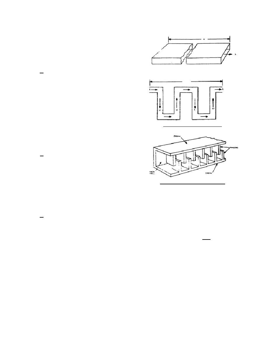
delay line is developed from a waveguide as shown
in figure 24. The movement of energy after the 6-
foot section of waveguide has been folded to an
overall length of 1 foot as indicated by S, S1 and S2.
b. The phase velocity in a straight
waveguide is comparable to the axial velocity of the
RF energy. To have effective velocity modulation
of the electron beam in a TWT, the axial velocity of
the modulating signal (RF) must be reduced. To
reduce the axial velocity of the RF energy in a
waveguide, the waveguide is folded as shown in B
of figure 24. Now the axial velocity of the RF
energy has been reduced six times. Folding a
waveguide is difficult and the result can be quite
Figure 24. Folded waveguide.
cumbersome. Instead of a folded waveguide, an
interdigital delay line is often used to reduce the
axial velocity of the RF signal. An interdigital delay
line is shown in figure 25.
c. The interdigital delay line can be
considered as a specially designed waveguide that is
open on the sides. The RF energy in the delay line
has electromagnetic fields that appear at the open
sides. This magnetic field will cause modulation
(bunching) in the electron beam as the beam passes
Figure 25. Interdigital delay line.
parallel to the delay line on its way to the collector.
The phase shifting of the RF energy is shown in B of figure 24 where S1 and S2 have opposing directions in the
delay line but have the same axial direction, S. The resultant RF field is similar to the one that is developed on
the helix shown in figure 26.
d. The M-type backward-wave oscillator is represented in figure 27. The size of the electron beam is
controlled by a beam-forming grid. The grid can control the number of electrons, but its main function is to
control the size of the electron beam while the accelerating anode controls the velocity of the electrons. The
magnetic field, B (which goes into the page in figure 27), is from a permanent magnet placed across
the tube.
The electric field, E, exists between the delay line and the sole of the tube.
The sole of the M-type tube is a nonemitting electrode and is usually the same length as the
344 L1
27


 Previous Page
