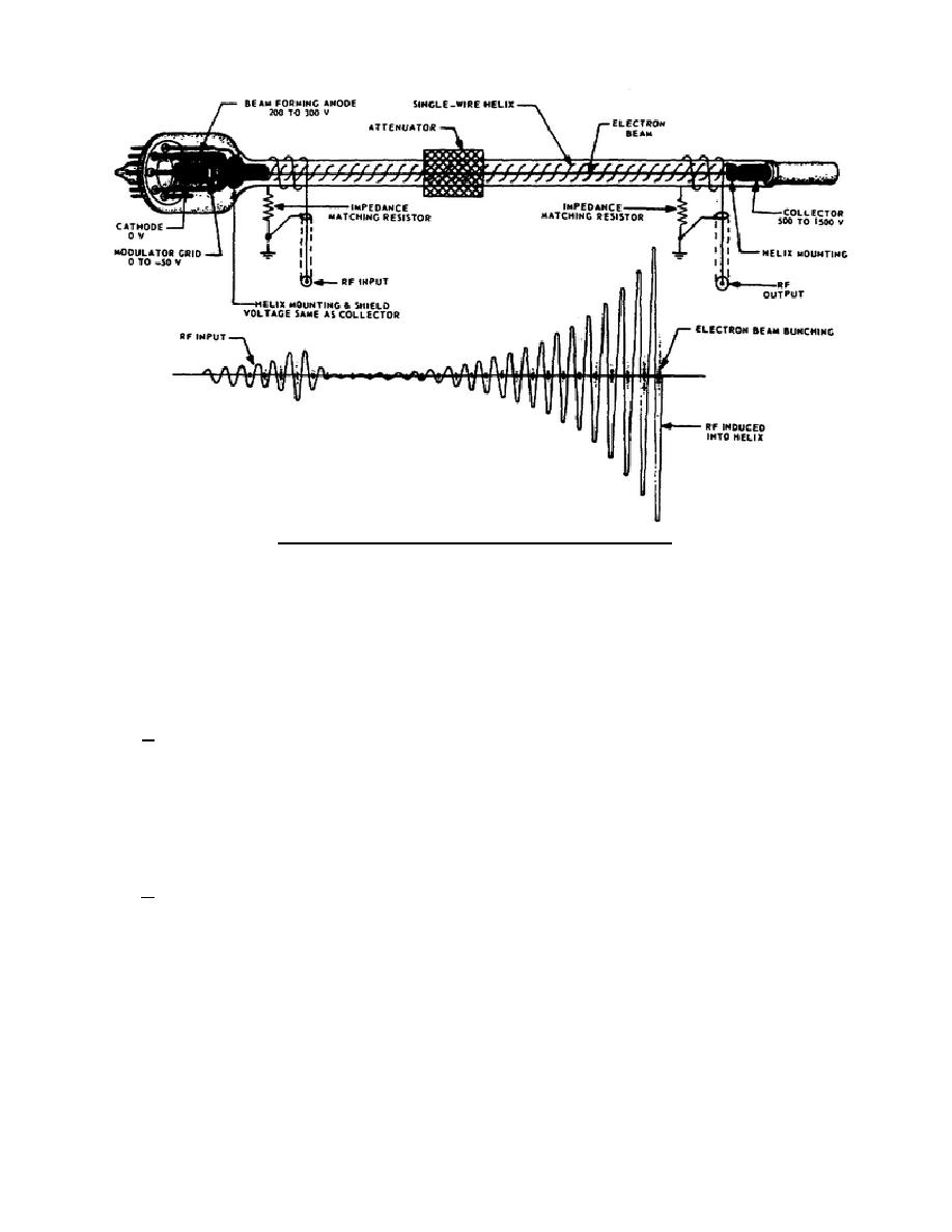
Figure 21. Velocity modulation in a traveling-wave tube.
feed back to the input side and cause oscillations. At the same time, though, the forward-going signal is also
attenuated as shown in the wave shapes. This does not have an appreciable effect because the electron bunches
are not affected by the attenuator. The electron bunches that emerge from the attenuator induce a new RF signal
on the helix, and it is of the same frequency as the input signal. The electron bunches and the newly induced RF
signal again start the interaction and amplification.
1-25.
COUPLING METHODS
a. Four methods are used to couple energy into and out of a TWT. The type of TWT, desired
bandwidth, and power requirements usually are the decisive factors in determining which type of coupling is most
efficient. In A of figure 22, the waveguide coupling is fairly simple. The waveguide is terminated in a
nonreflecting impedance and the helix is inserted into the waveguide like a quarter-wave stub. The efficiency of
this system is good but the waveguide has a much higher Q than the TWT. This means that the broadband
characteristics of the TWT are considerably suppressed in that the entire bandwidth of the TWT is not available
for amplification.
b. In B of figure 22, the cavity coupling is similar to the waveguide coupling. The helix is inserted in
the cavity so that the E field in the cavity will induce RF energy into the helix. The cavity is excited by a
coupling probe or a coupling loop on the input side; the same method is used on the output side, but the action is
reversed.
The helix excites the cavity and the probe or loop removes the energy from the
cavity.
At higher frequencies, the size of the cavity is small and the amount of output
power must be limited to avoid serious arcing.
Cavities can be made to resonate over a
344 L1
23


 Previous Page
