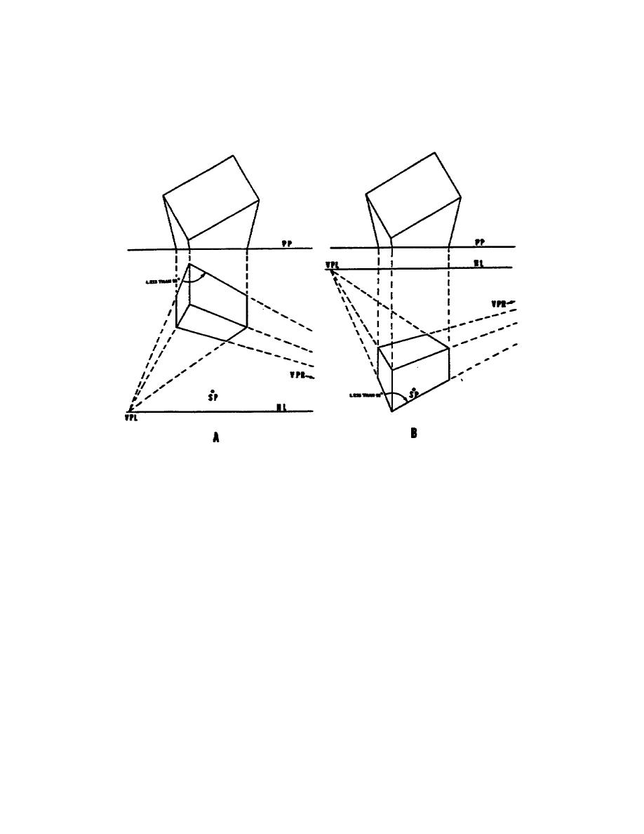
4. However, if the object is placed too high above the eye level or too low
below it, the effect will be one of distortion.
A block drawn in these
positions will cease to look right as shown in Figure 11. (When the station
point is too close to the object, there will be a similar distortion.) The
angle indicated in the figure should never be less than 90 and preferably
not less than 100.
Figure 2-6. A. Object placed too high above eye level
B. Object placed too low below eye level
5. To overcome distortion such as that illustrated in Figure 2-6, the
station point may be moved further from the object, or the picture plane and
object may be considered tilted at an angle to each other so that a third
vanishing point is needed for the third set of parallel lines in the
drawing.
6. Inclined lines and planes have vanishing points similar to horizontal
vanishing points.
If you are constructing a perspective from plan and
elevation views, locating the vanishing points for the inclined lines will
involve further preliminary projection.
a. Figure 2-7 shows an object being constructed in a manner similar to
the previously discussed perspective drawings. However, the object contains
three pairs of parallel lines defining three inclined planes. One accurate
method of constructing the perspective view is to project it without using
vanishing points similar to Figure 2-2. To construct this object using only
the plan view and elevation for measuring purposes, you must also locate
vanishing points for the inclined lines.
18


 Previous Page
