3.
The circuit illustrated in Figure 1-20 is, for all practical purposes,
identical to that in Figure 1-19 except for the resistance values used.
For
instance, when the function switch is set at 20K ohm/V and the range switch at any
position, the circuit reduces to the simplified diagram illustrated it Figure 1-20.
Again, the value of R depends upon the position of the range switch, as shown in
the accompanying table.
The total resistance, including the 1700 ohmmeter
resistance, provides a 20,000 ohms-per-volt sensitivity for all ranges selected.
4.
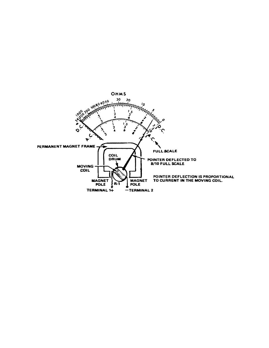
While we are talking briefly about DC voltage measurements, note two simple
things that can cause damage to the meter movement. Refer to Figure 1-21 and note
what happens when the meter leads are connected backwards in the circuit.
The
meter needle deflects in the opposite direction and is damaged because it is driven
into the stop, or, forced off scale.
Figure 1-21.
Meter damage
5. Suppose the meter is connected to a source of voltage greater than that which
produces full-scale deflection. In this case the current through the movable coil
exceeds the 1mA for which the coil is designed and forces the meter needle off the
scale and may burn out the meter coil.
24


 Previous Page
