Learning Event 6:
DETERMINE THE VALUE OF R FOR AC VOLTAGE MEASUREMENTS
1.
The measurement of AC voltage is a procedure very similar to the DC voltage
measurement procedure just discussed.
Again, the controls on the front panel of
the PSM-6 are the function and range switches. With the function switch set at ACV
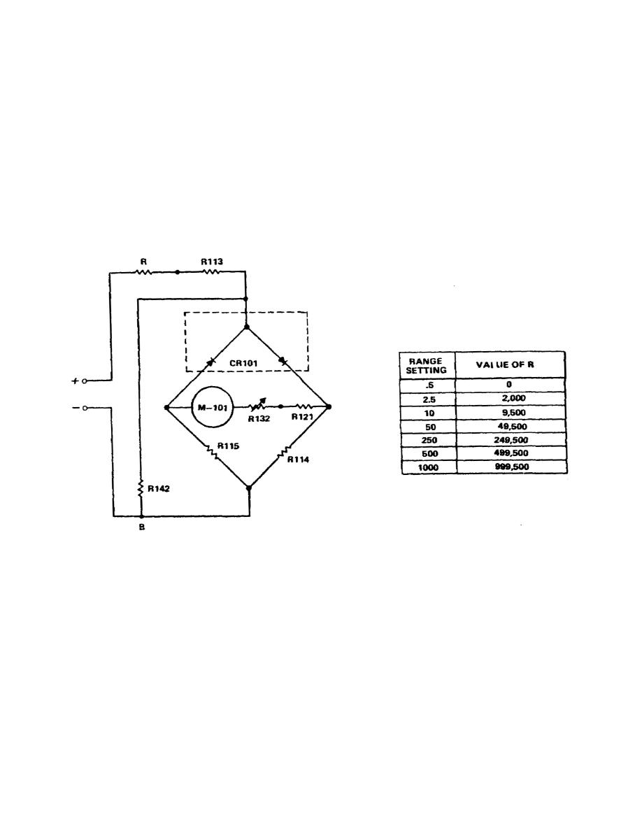
and the range switch at any position, the circuit is basically the one shown in
Figure 1-22, with the values of R as shown in the accompanying table.
The ACV
ranges are also designed for a sensitivity of 1000 ohms/volts, and the total
resistance between points A and B should therefore be 450 ohms. The two rectifier
sections of CR101 rectify the incoming AC voltage, and the resulting pulsating DC
is read on the meter. Resistor R132 is a variable resistance, set at the factory,
to provide
compensations
for
variations
in
rectifier
characteristics
and
temperature correction.
Figure 1-22.
AC voltage measurement circuit
2.
The same basic precautions applying to AC voltage measurements apply to DC
measurements except that it is not necessary to observe polarities. One additional
precaution that should be observed, however, is one not necessarily related to
safety but one which results in proper use of the meter in AC voltage measurements.
The AC voltmeter section of the PSM-6 is designed to handle frequencies up to about
1000 hz. Above this frequency the voltage readings are subject to inaccuracies due
to inductive reactance.
25


 Previous Page
