Learning Event 7:
DETERMINE THE RANGE SELECTION USED IN RESISTANCE MEASUREMENT
1.
Although it uses the same basic meter movement, as shown in Figure 1-21, the
circuitry is quite different.
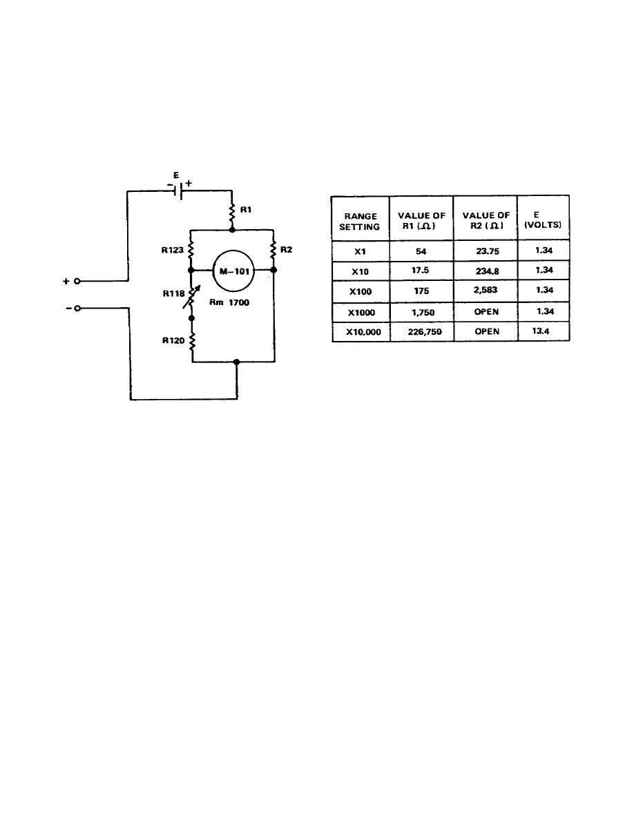
The circuit contains a battery in series with the
meter, as shown in Figure 1-23. The ohms zero control R118 allows you to zero the
meter for considerable drops in battery voltage.
With the meter leads shorted
together, adjust the variable resistor to produce a full-scale reading on the
meters.
Figure 1-23.
Resistance measurement circuit
a. The full-scale reading indicates zero resistance.
When you insert a 50-
ohm resistor between the leads, the current in the circuit is reduced and the meter
no longer reads full scale.
In other words, the size of the resistor inserted
between the leads determines the current through the meter and the amount of meter
deflection.
b. The scale is calibrated to read directly in ohms. A range switch allows
you to select ranges of x1, x10, x100, or x10,000. For example, a direct reading
of 67 on the scale with the range switch at x100 means that the circuit has a
resistance of 67 x 100 or 6700 ohms.
2.
Look at Figure 1-24 and see what else we should recall about measuring
resistance with the meter.
This figure shows a portion of the synchronizing
circuit located in a typical modulator.
Notice that the ohmmeter is connected
across R630.
Should you expect to get a reading of 100 on the meter?
No, you
should not! If you analyze Figure 1-24 more closely, you will see that the current
from the meter has two paths.
One path is from point A to terminal 7 to T603,
through the transformer winding to terminal 8, and return to point B.
26


 Previous Page
