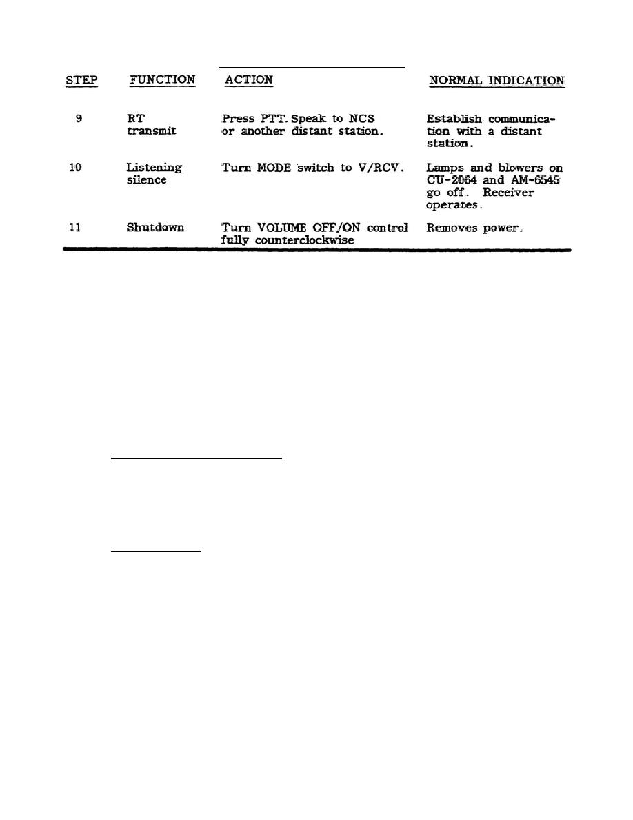
Table 5.
Op check (continued).
10. ABNORMAL INDICATIONS. Any abnormal indications must be
entered on DA Form 2404
(Equipment Inspection and Maintenance Worksheet). Abnormal
indications show a need
for systems troubleshooting to determine which cable
or accessory requires
replacement or repair or which component requires evacuation
to higher maintenance.
11. AUDIO INDICATORS. Audio indicators are provided by the RT-1209. They indicate
a low-voltage condition (a clicking sound, particularly in the receive mode), a
tuning fault (a beeping 1-kHz tone), fine tuning (a steady l-kHz tone), and a
disturbance of antenna condition during transmit (a single 1-kHz beep).
Transmit
Is locked out during any tuning sequence, but you must know what these audible
tones mean and when to expect them. A tune fault tone is heard from turn-on until
warm-up is achieved.
12. PROCEDURES FOR OPERATION.
a. Voice or CW key connections. If voice or CW key operation is to be used,
make the connections. For voice operation, connect the handset to the HANDSET jack
on the amplifier-converter or to the upper AUDIO jack on the RT. (Press connector
inward and twist clockwise.) The short audio cable is connected between the AUDIO
jack on the amplifier-converter and the lower AUDIO jack on the RT.
For CW key
operation, connect the CW key to the AUDIO jack on the amplifier-converter.
Connect the headset to the AUDIO jack on the RT.
b. Data operation.
For operations involving data transmission, connect the
data input to either the AUDIO jack on the amplifier-converter or to the upper
AUDIO jack on the RT.
22


 Previous Page
