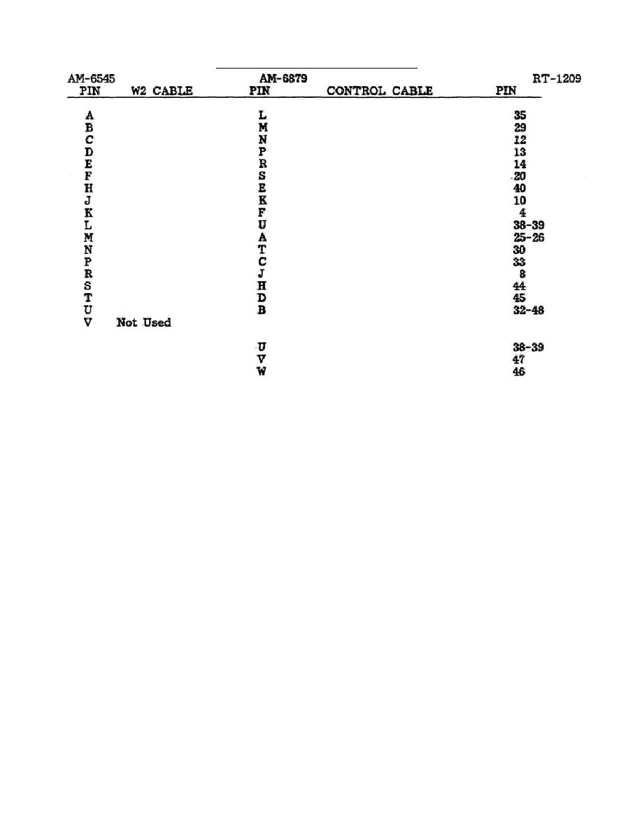
Table 6..
Cable pin assignments.
NOTE:
Some wires in RT control cable have multiconnection in the RT and are found
at any of the pin numbers listed.
Pins U, V, and W are not directly
connected through the AM-6879. Therefore, they must be checked separately.
Pin V of J6 goes to the center pin of J7 and pin W of J6 goes to the shell
of 7. Pin U of 6 goes to pin U of J5 through the 3-amp fuse of the AM-6879
and should read a very low ohmic value. All other connections go straight
through and should read 0 ohms between the same pin number from J5 to J6.
This information can be used to determine if there are opens or shorts in
the interconnect cables or AM-6879, to isolate a problem to cables or AM-
6879, or to eliminate them from consideration.
17. POWER CONTROL. Power is controlled through the AM-6545 power distribution by
the RT.
Therefore, if the checks in paragraph 16 eliminate cables and AM-6879
(remember the fuse) as the source of a power problem, cable CX-4720 has been
checked for power. A power problem can be caused only by the RT or AM-6545. The
only method available at this time for the organizational repair person to
troubleshoot such a problem is to substitute a known good RT. If this corrects the
problem, you DX the RT. If it does not correct the problem, DX the AM-6545. The
AN/GRC-193 turns itself off if voltage goes too high or if it overheats.
If
cooling louvers clog up and cause overheating, they can be washed out with soap and
water.
The PA and coupler are both sealed units.
This must be checked before
determining that a malfunction really exists in the radio set. If the PA or CPLR
lamp lights, try to clear
27


 Previous Page
