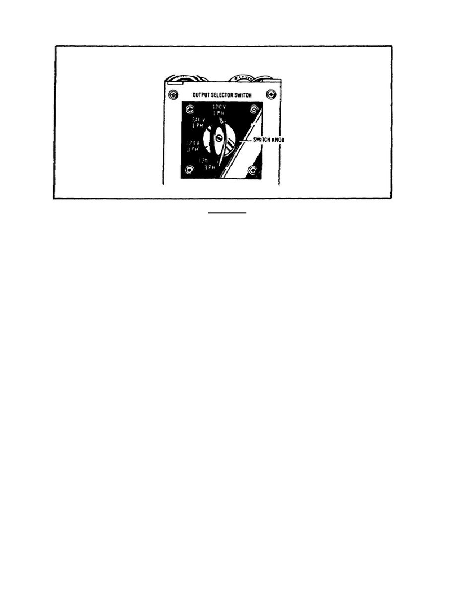
FIGURE 8.
OUTPUT SELECTOR SWITCH.
WARNING
DO NOT CONNECT LOAD TERMINALS WHILE THE GENERATOR
SET IS OPERATING.
(2) For 240 volts single phase current, move switch knob to 240
V, 1 HR position.
(3) For 120 volts three phase current, move switch knob to 120
V, 3 PH position.
(4) For 120/208 volts three phase current, move switch knob to
120/208 V 3 PH position.
(5) For 120 volts single phase, connect cables to terminals L1
and L2.
(6) For 240 volts single phase, connect cables to terminals L1
and L2.
(7) For 120 volts three phase, connect cables to terminals L1,
L2, and L3.
(8) For 120/208 volts three phase (four wire), connect cables
to terminals L0, L1, L2, and L3.
e. Generator set controls and instruments.
To properly operate
the generator set MEP-016A, you must understand the purpose and
normal reading of the generator set controls and instruments.
(See
Figures 9 and 10.)
(1) The CHOKE CONTROL level is normally open.
(2) The GOVERNOR control is in the GOVERN position.
10


 Previous Page
