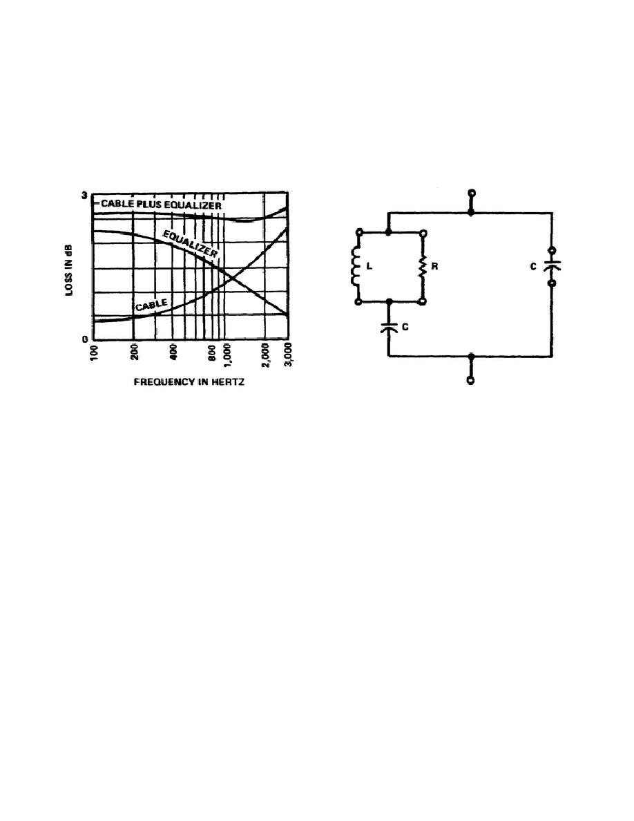
(2) Although it is impossible to make the frequency response of this system uniform, a good
deal of improvement could be acquired by selecting a suitable equalizer circuit with correct component
values.
(3) A limitation of the equalizer is the inability to make up or compensate for load changes.
Such changes may occur during switching procedures. Therefore, equalizers can be switched in or out
of the Load circuit. Also, equalizers have a definite insertion loss, and this loss may be compensated by
increasing amplitude. Figure 5-2 shows a typical equalizer configuration.
Figure 5-2. Typical equalizer configuration
Figure 5-1. Cable, equalizer, and system
frequency responses
b. Attenuator. An attenuator is a network designed to reduce the amplitude of a signal. For this
reason the circuit is usually passive rather than active. These circuits are beneficial for calibrating or
other sensitive measurements.
(1) If the attenuator is well designed, then the amount of attenuation is continuous over the
entire range of frequency in the system to be checked. Attenuators pose no reactance; therefore, no
phase shift. These circuits are built to handle various input and output impedances; therefore, these
impedances must be matched properly or the attenuator will function improperly. Figure 5-3 shows two
different passive attenuators made of non-inductive resistors.
(2) Circuit A is called a pre-network attenuator.
(3) Circuit B is called a T-network attenuator.
Both circuits function from the audio-
frequency range to the VHF spectrum.
47


 Previous Page
