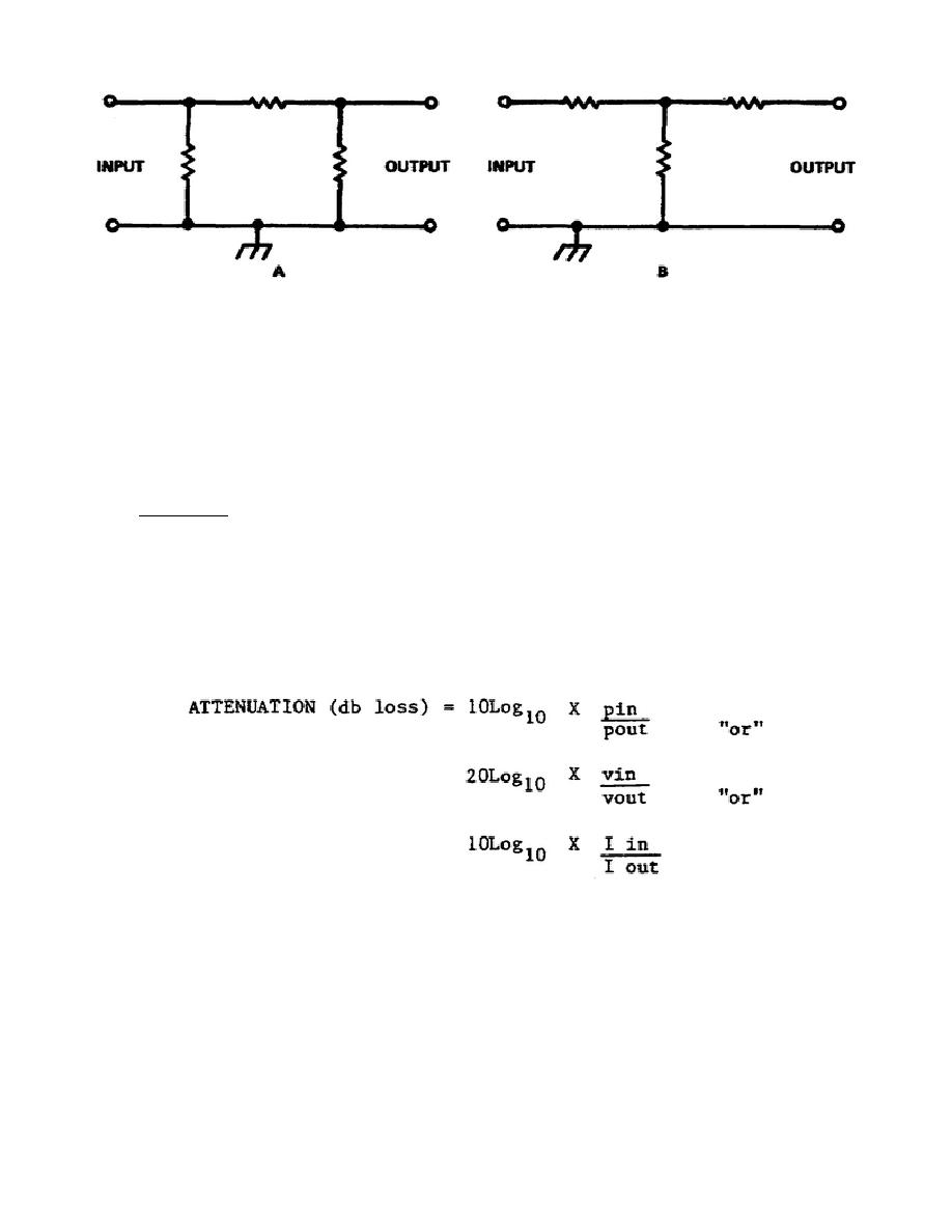
Figure 5-3. Attenuator. Attenuators often constructed from noninductive resistors. Here, two such
devices are shown at A the pre-network and at B the T network. These attenuators are for use in
unbalanced circuits
(4) However, from UHF and above the resistors begin showing inductive reactance. This
happens because the wavelength is so short that the leads are quite long electrically; therefore, the
attenuators no longer perform the function intended for them. Attenuators must be especially designed
to suit the short wavelengths of the VHFs. These circuits must be physically small.
2.
Attenuation. Attenuation is the decrease in amplitude of a signal between any two points in a
circuit, usually expressed in decibles. Attenuation is the exact opposite of amplitude and can be defined
for power, current, or voltage. Occasionally attenuation in a particular circuit is sometimes expressed as
a ratio.
a. As an example, the loss of signal in amplitude from say plus or minus 5 volts peak to plus or
minus 1 volt peak is an attenuation factor of 5. This loss in decibles may be calculated using one of the
following equations:
b. Keep in mind that attenuation is the opposite of amplification. If the amplification factor is
X db, then the attenuation factor is -X db.
48


 Previous Page
