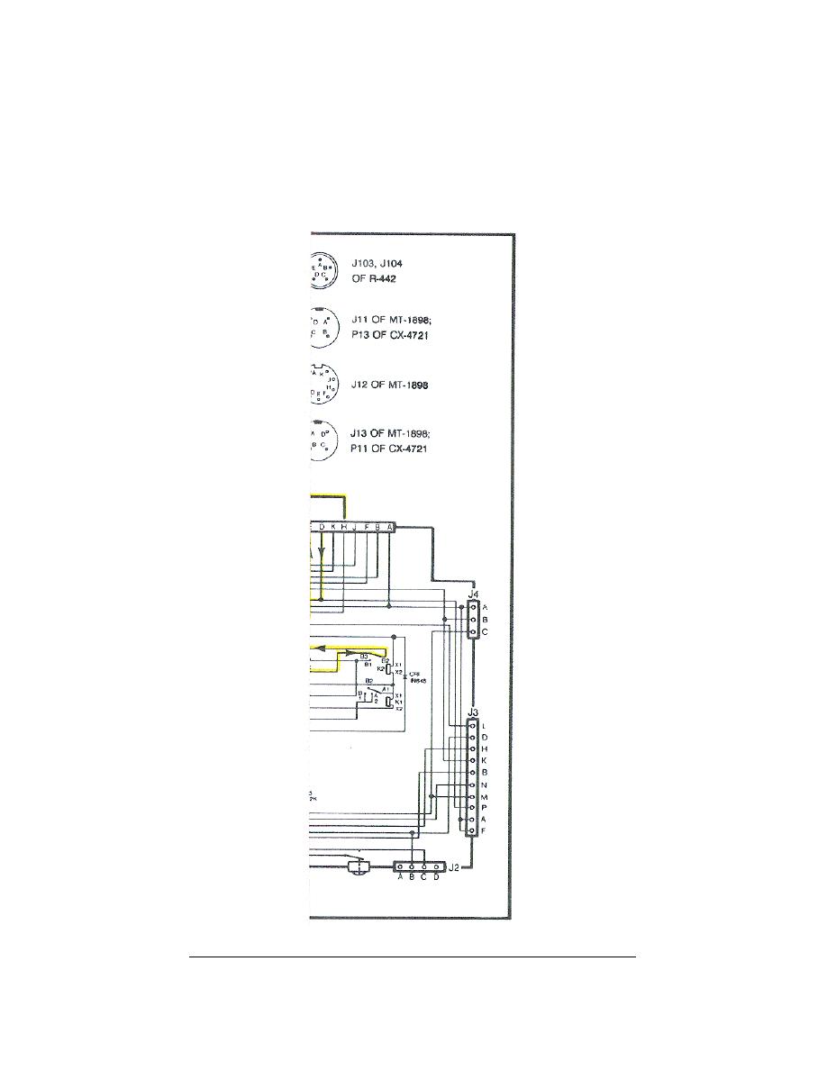
X-MODE), the signal is applied, through the R-442 and MT-1898, to the J-
3514/U P1 pin D (X-MODE IN). Within the J-3514/U the signal (entering on P1
pin D) is applied to K2 B3 to B2. Then the signal is applied back to the
MT-1898 J12 pin E, to the R-442 P201 pin E (X-MODE OUT), and to the AF A-
5000. In the AF section the signal is divided into three circuits: speaker
out, phone out, and monitor out.
(Trace these circuits on your system
diagram.)
Figure 92.
R-442 receive signal path (continued).
105a


 Previous Page
