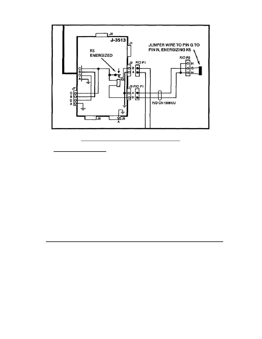
Figure 103.
Jumper pin G to pin N.
(4) Test procedure 81. Remove the jumper wire from the CX-13061/U.
Remove the CX-13061/U from the J-3513/U J3. Measure continuity on the CX-
13061/U, P2 pin T to P1 pin L.
If infinity is measured, the CX-13061/U is bad.
If zero ohms is measured, disassemble the MT-1029.
Remove P1 from J22.
Measure continuity on the MT-1029 J24 pin P to J22 pin P.
If infinity is measured, the MT-1029 mount is bad.
If zero ohms is measured, the J-3513 is bad.
c. Receive signal path circuit possible bad items (lamp lights). The
symptom, A-RT call lamp lights but no alarm beeps are heard in the handset,
is observed. When the handset is moved to the KY-57 audio connector, alarm
beeps are heard.
This indicates the receive signal path is bad.
This
symptom is caused by an open circuit. Trace the receive signal path circuit
and identify the following possible bad items of equipment: CX-13062/U and
J-3513/U (Figure 104). (Dashed line on figure 104 represents circuits that
were checked good in plain text.)
126


 Previous Page
