(3) Microwave energy in the circulator is prevented from circulating in a counterclockwise direction
by the ferrite material making up the circulator. There are some cases where the energy is passed
in a counterclockwise direction, and circulation in a clockwise direction is prevented. This is
done to prevent signal interference.
c. As shown in figure 90, the two
microwave signals are transmitted to the distant
station, received by the antenna system, and applied
to a circulator on the waveguide.
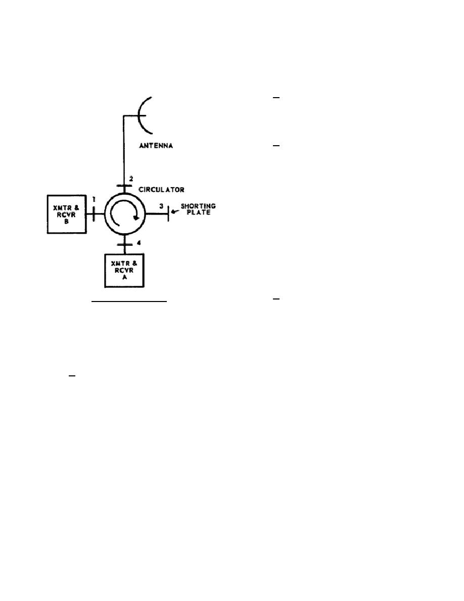
d. The receiver path through the circulator
is as follows: assuming the circulator is connected as
shown in figure 91, the two microwave signals enter
the circulator at port 2 and emerge at port 3. The
shorting plate reflects both signals, which are
circulated on to port 4. The signals emerge at port 4.
The bandpass filter associated with receiver A
passes the appropriate signal to receiver, but reflects
the other signal back to the circulator. This signal
reenters the circulator at port 4, is circulated
clockwise, and emerges at port 1. The bandpass
filter associated with receiver B passes the signal to
the receiver.
2-19.
MODE LAUNCHERS
a. Mode launchers are used to convert RF
Figure 91. Circulator.
energy from one type of mode to another. They are
usually needed when a rectangular waveguide is
joined to a circular waveguide. When used to join these two sections together, the mode launcher will change the
TE rectangular mode to the TE circular mode that is required for propagation in the circular waveguide.
Subscripts are used to provide additional mode information. Mode launchers are also used to convert circular
operating modes to rectangular operating modes.
b. A functional diagram of a mode launcher is shown in figure 92. Details A and B show the standard E
and H field distribution pattern for the TE mode that exists in rectangular waveguide and the TE mode that is
required for the circular waveguide. In detail C, the arrows indicate the direction of the E field in the mode
launcher. For simplicity, the H field is not shown, since the primary consideration here is the conversion of the E
field. As shown in detail C, the input signal is split so that one-half of the power is fed into each of the two
branches. The signal in each branch is again split so that one-quarter of the original power is applied to each of
the four ports in the circulator. These four signal components are then recombined in the circulator with very
little loss, so that nearly 100 percent of the original input power is converted to the required circular TE mode. It
should be observed that the E field lines in the rectangular waveguide are aligned in such a direction as to
automatically set up the required TE circular mode when the four signal ports are added.
344 L2
85


 Previous Page
