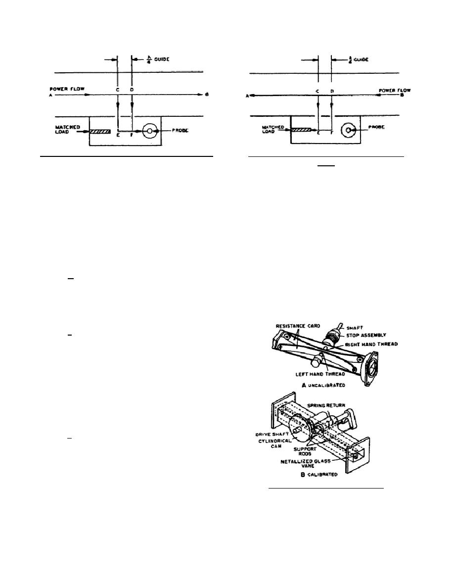
Figure 87. Directional coupler, incident power flow.
Figure 88. Directional coupler, reflected power
flow.
out-of-phase waves cancel each other and no power is delivered to the load. Figure 88 shows the same coupler
with power flowing in the reverse direction. Again samples are removed at points C and D. The two paths, D-F-
E and D-C-E, are the same length, and the two samples arrive at point E in phase and are absorbed by the load.
However, path D-C-E-F is a half wavelength longer than path D-F, and the resulting 180, phase shift causes
cancellation at point E. The result is that the coaxial probe receives energy only from a wave traveling from left
to right in the main line, and any reflections causing power to flow from right to left have no effect upon the
coupled signal. In practice, the attenuation between the coaxial output and the main-line power flowing from left
to right is usually adjusted to be over 20 db and is called the nominal attenuation (or simply the attenuation) or the
coupling factor.
c. Directional couplers serve as accurate, stable, and relatively broad band coupling devices, which can
be inserted into a transmission line so as to sample either incident or reflected power. This sample is then used by
test instruments to analyze equipment operation.
2-17.
ATTENUATORS
a. Attenuators in present use are classified
as dissipative and nondissipative.
The
nondissipative uses a waveguide which is operated
below its cutoff frequency. Attenuation is achieved
through mismatch, which reduces the power output
by reflecting a portion of the incident power. The
amount of mismatch depends upon the length and
the size of the waveguide. In the dissipative type,
the difference between the output power levels is
absorbed within the transmission system.
b. Both fixed and variable attenuators for
rectangular waveguides usually employ resistive
plates inserted parallel with the electric field. In
Figure 89. Waveguide attenuators.
344 L2
83


 Previous Page
