2-13.
JOINTS
It is almost impossible to construct an entire waveguide system in one piece. The waveguide system is
made up in sections and the sections are connected by special joints. It would seem reasonable to assume that
joining two waveguide sections would only require that the sections be the same size and fit tightly at the joint.
Unfortunately, it is not as simple as this because the slightest irregularity in the joint will cause reflections,
standing waves, and loss of energy. The two main types of joints are permanent and semipermanent.
a. Permanent Joints. The permanent-type joint has no irregularities and does not disturb the
electromagnetic energy in the waveguide. The waveguide sections are machined within a few thousandths of an
inch and then welded together. The result is a hermetically sealed and mirror-smooth joint. The permanent joint
cannot be used where the installation is in limited space, and the waveguide must be installed in sections. Also, it
is sometimes necessary to remove waveguide sections for maintenance and repairs. When this situation occurs, it
is more desirable to use the semipermanent joint.
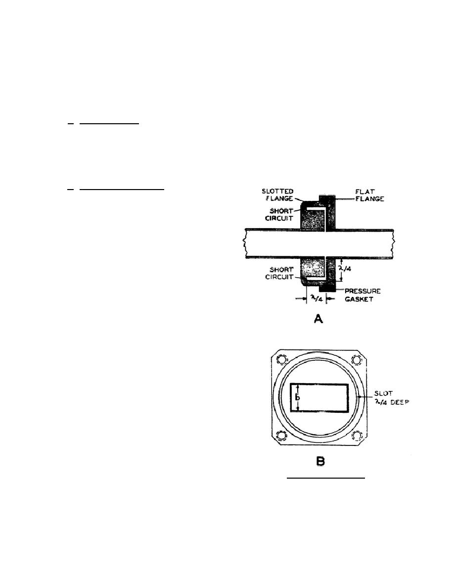
b. Semipermanent
Joint.
The
semipermanent joint most commonly used is the
choke joint. A cross-sectional view of the choke
joint is shown in figure 81. It is made up of a flat
flange and a slotted flange. The slotted flange
shown in B of figure 81 has a groove, or slot, that is
one-quarter wave deep. This slot is one-quarter
wave distance from the center of the wide side of the
waveguide. In A of figure 80, notice that the depth
of the groove plus the distance from the waveguide
add up to a distance of one-half wavelength. The
bottom of the groove is shorted so that the half wave
now reflects a short where the waveguide walls are
joined together. Electrically this creates a short
circuit at the junction of the two waveguides. This is
just as effective as a permanent joint.
(1) The two sections can be separated as
much as one-tenth of a wavelength
without much loss of energy at the
joint. This separation allows a
gasket to be inserted to seal the
waveguide. In some installations
the waveguide is pressurized with
dry air or
Figure 81. Choke joint.
344 L2
79


 Previous Page
