2-10.
IMPEDANCE MATCHING
a. Waveguide Termination. When energy
is coupled into or out of a waveguide, there should
be an impedance match between the generator, the
coupling elements, the waveguide, and the load. In
this respect, the waveguide is affected the same as a
two-wire line. Unless the waveguide is terminated
in its characteristic impedance, standing waves will
be created. The characteristic impedance of the
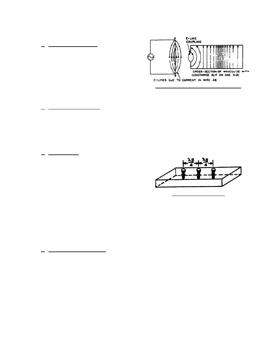
Figure 72. Excitation through the window.
rectangular waveguide may be of any value,
depending on the dimensions of the waveguide and the frequency of the energy coupled to it.
b. Characteristic Impedance. Since a waveguide is a single conductor, it is not easy to define the
characteristic impedance. You may, however, think of the characteristic impedance as being approximately equal
to the ratio of the strength of the electric field to the strength of the magnetic field for energy traveling in one
direction. This ratio is equivalent to the voltage-to-current ratio in a coaxial line that has no standing waves. In
the rectangular waveguide, the characteristic impedance may vary from approximately 0 to 465 ohms. The
characteristic impedance may also be expressed in terms of the free-space wavelength and the wavelength in the
waveguide.
c. Tuning Screws. Impedance matching in
a waveguide is done with reflector elements. Any
obstruction in a waveguide can act as a reflector
element if the obstruction does not consume power
and the longitudinal dimension of the element
projecting into the waveguide is small compared
with the wavelength in the waveguide. The tuning
screws (fig. 73) are threaded cylindrical posts that go
Figure 73. Tuning screws.
through the top of the waveguide. A single tuning
screw may be used, but the positioning and adjusting of this screw is very critical. Three tuning screws are
usually used. These screws are one-quarter wavelength (in the waveguide) apart. When the tuning screw extends
less than a free-space quarter wavelength into the waveguide, it introduces capacitance into the waveguide. An
inductance is introduced into the waveguide when the tuning screw is more than a free-space quarter wavelength.
When using this element, the inductive tuning is usually not used because of the danger of voltage breakdown. If
the tuning screws are placed in the waveguide where they are parallel with the electric field, they can be adjusted
for a minimum standing-wave ratio.
d. Reactive Plates (Inductive). Small fins or plates are sometimes used to match impedance in a
waveguide. Figure 74 shows a number of reactive plates that will introduce inductance or capacitance in a
waveguide. These reactive plates are put into the waveguide so that they are at right angles to the direction of
propagation. The position of the plates in A of figure 74 introduces an inductive reactance. The wider the space
between the plates, the greater the inductive reactance.
344 L2
75


 Previous Page
