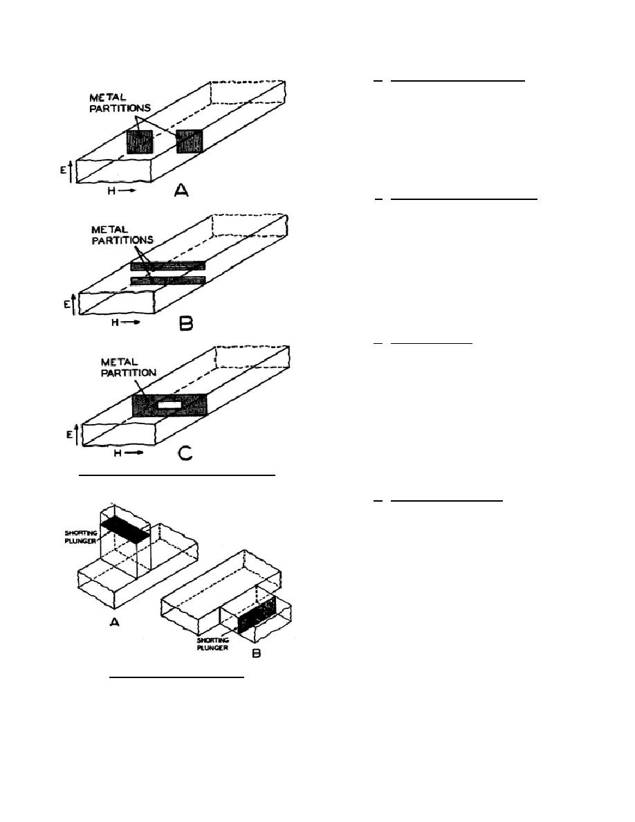
e. Reactive Plates (Capacitive). When the
reactive plates are arranged as shown in B of figure
74 a local E field and higher modes of operation are
set up between the edges of the plates. These
oscillations cannot be propagated but they do
introduce a capacitive reactance into the waveguide.
The capacitive reactance increases as the space
between the plates is increased.
f. Reactive Plates (Resonant).
By
combining both types of plates and leaving an
opening, as shown in C of figure 74 we have the
equivalent of a parallel resonant circuit. If the
dimensions of the reactive plates are correct, the
inductive reactance will equal the capacitive
reactance and the opening will present a pure
resistance. At resonance, a parallel resonant circuit
offers a high resistance. In this condition the
waveguide has in effect a high resistance across it.
g. Waveguide Stubs. Waveguide stubs, as
shown in figure 75 are sometimes used as reactive
elements. These stubs may act as an open or short
circuit to the waveguide in the same manner as stubs
used in a two-wire line. Shorted stubs are used to
prevent undesired radiation of energy. When placed
as shown in A of figure 75 the stub acts as an
impedance in series with the line and is called a
series stub. In B of figure 75 the stub acts as a shunt
impedance across the waveguide and is called a
shunt stub.
Figure 74. Reactive plates in a waveguide.
h. Waveguide Transformer. An impedance
transformer is used to change from one value of
impedance to another. One type is the tapered-line
transformer (fig. 76). The dimensions of the
waveguide are varied very gradually by the tapered
section. This changes the characteristic impedance
of the main waveguide to the value of the load. The
tapered section must be longer than two wavelengths
of the signal in free space.
The impedance
transformation is gradual and is effective over a
wide band of frequencies.
Figure 75. Waveguide stubs.
344 L2
76


 Previous Page
