2-8. MODES
a. The shape, or pattern, of the electric and magnetic fields in a waveguide is determined by the
frequency of the input signal and the size of the waveguide. This pattern will be called the field configuration.
b. The various field configurations are known as modes. The mode is identified by the field that is
transverse, or perpendicular to the direction of propagation. The two main classes of modes are the transverse
electric (TE) and the transverse magnetic (TM). A system of subscripts is used to further identify the different TE
and TI modes that can occur.
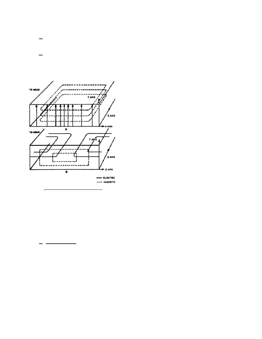
(1) In a TE mode, all components of the
electric field lie in a plane that is
transverse, or perpendicular to the
direction of propagation, as shown
in A of figure 68. The field is
propagated along the Z axis. The
distribution of the electric field is
along the X axis or along the width
of the waveguide, and it is parallel
to the Y axis. The magnetic field is
parallel with the X and Z axes. The
mode therefore is a TE, or
transverse electric, mode.
(2) In the TM mode shown in B of
figure 68, the magnetic field is
parallel with the X and Y axes and it
is also perpendicular to the Z axis or
direction of propagation.
The
electric field is parallel with the X
Figure 68. TE and TM modes.
and Z axes.
Section III. WAVEGUIDE DEVICES
2-9. COUPLING METHODS
Energy may be transferred either to or from a waveguide with the same efficiency. The three basic
methods of coupling energy into and out of a waveguide are the probe, loop, and window methods.
a. Probe Coupling. A coupling probe is a small metallic conductor inserted in the waveguide, usually
parallel with the lines of the electric field. The waveguide shown in figure 69 is to be operated in the TE mode.
For this mode, the probe is inserted in the center of the wide side of the waveguide. The electric field extends
across the width of the waveguide, but it is maximum at the center.
344 L2
72


 Previous Page
