closed loops, since magnetic lines of force cannot otherwise exist. The distribution of both fields is shown in
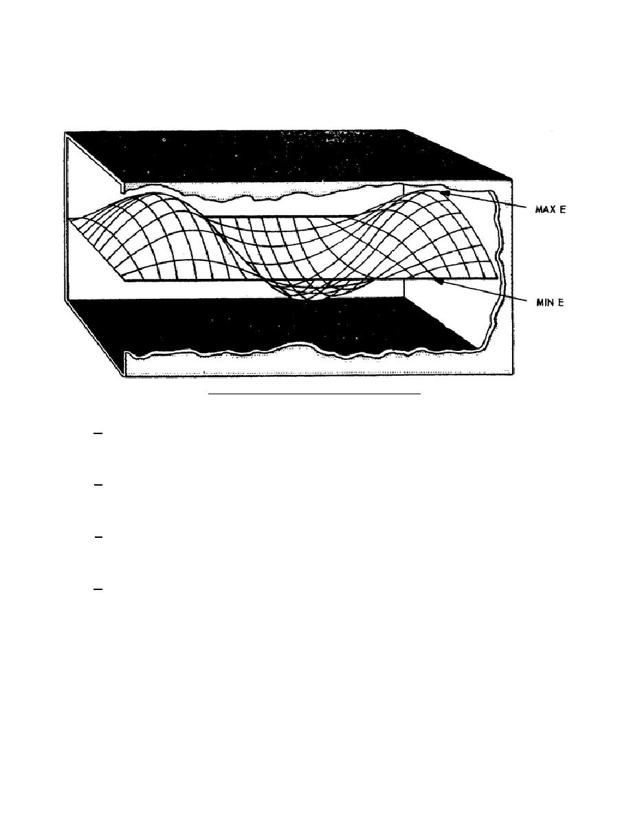
figure 64. The intensity of the magnetic field varies sinusoidally down the center of the waveguide the same as
the electric field, but perpendicular to the electric field. Figure 65 may give you a better idea how the E lines are
distributed in a waveguide.
Figure 65. E field distribution in a waveguide.
d. The electromagnetic energy is put into the waveguide by an antenna or a radiator. The antenna
radiates in all directions. There are only two angles of radiation at which proper addition and cancellation take
place to produce a wave that fulfills the boundary conditions required to sustain energy propagation.
e. Figure 66 shows electromagnetic waves put into a waveguide by an antenna in the form of
wavefronts. The wavefronts bounce off the walls and cross at an angle. The antenna is oriented so that these
wavefronts strike the sidewalls at the incident angle needed to obtain the desired field pattern in the waveguide.
f. When wavefronts crisscross, the two fronts add at the center of the waveguide and cancel at the sides
of the waveguide. The resultant field distribution has a sine wave pattern across the width of the waveguide, but
at some angle to the waveguide wall.
g. As the frequency of the energy in the waveguide is decreased, the incident angle decreases. As the
angle approaches zero, the direction of propagation is back and forth between the walls of the waveguide instead
of down the waveguide. At this point we have reached the cutoff frequency and the energy below this frequency
is dissipated by the resistance of the walls of the waveguide.
344 L2
70


 Previous Page
