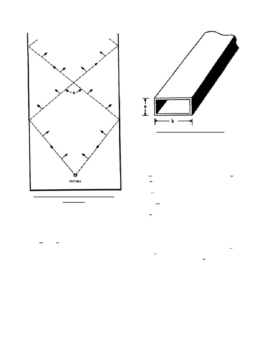
Figure 67. Waveguide dimensions.
2-7. SIZE
The correct size of a waveguide is
determined by the frequency (or wavelength) of the
energy that will be fed into the waveguide. Figure
67 shows that the narrow walls, or sidewalls, are
side a, and the top and bottom walls are side b. If
side b is one-half wavelength or less, cutoff will
occur. So the cutoff frequency can be determined
when b = /2.
Figure 66. Crisscrossing plane waves in a
waveguide.
a. To have energy travel through the
waveguide shown in figure 3-6 with minimum loss,
side b should be greater than one-half wavelength,
but less than 1 wavelength. The lower and upper
limits can be expressed, respectively, as /2 and . For the ideal waveguide the arbitrary figure for the width is b
= 0.7.
b. Side a of the waveguide is not critical since the field does not vary in this direction. However, the
dimension must be considered when determining the amount of power the waveguide must handle. Side a, the
smaller dimension, is where arc-over may take place. Also, if side a is greater than one-half wavelength, then a
half-cycle of vertical variation is possible and the signal will be attenuated. Therefore, side a should be smaller
than /2. The outside dimensions of a rectangular waveguide should be such that the width is twice the height.
The ratio of the inside dimensions is somewhat greater than 2 to1.
344 L2
71


 Previous Page
