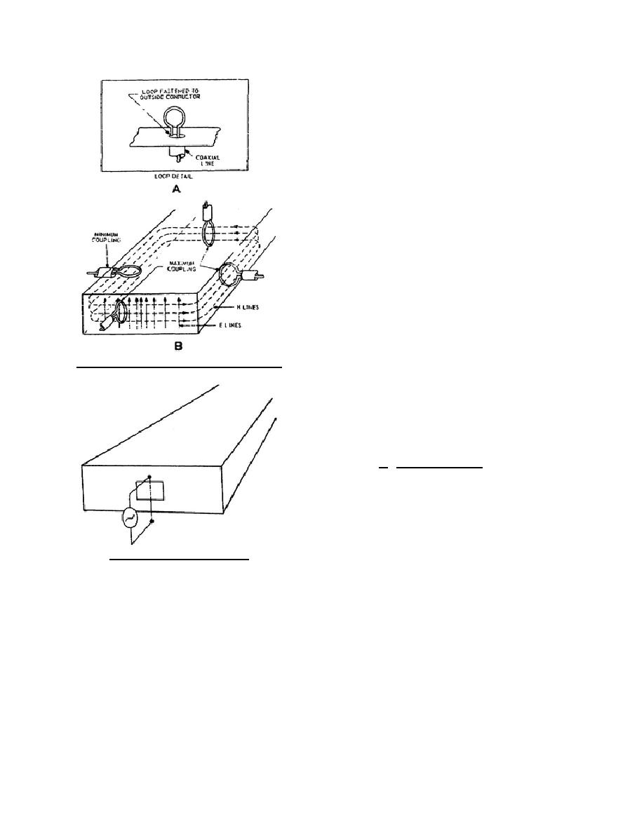
builds up a magnetic field around
the loop. The magnetic field then
expands and fits into the waveguide.
This pattern moves down the
waveguide at the phase velocity.
The location of the loop for
maximum
coupling
to
the
waveguide is at the place where the
magnetic field is of greatest
strength, as shown in B of figure 70.
The construction and mounting of a
loop is shown in A of figure 70.
(2) Loop coupling is the most common
method of coupling energy into or
out of a waveguide. It offers no
loading effect to the waveguide
because it is inductive coupling,
whereas the probe is capacitive
coupling. If less coupling is desired,
the loop may be rotated so that it
encircles a smaller number of
Figure 70. Orientation of the coupling loop.
magnetic lines, as shown in B of
figure 70 (left side). Usually it is
desirable to have maximum
coupling.
The loop is also a
broadband coupling device and will
handle high-power signals.
c. Window Coupling. The third method of
coupling energy into and out of a waveguide is the
iris, aperture, slot, or window coupling. Energy can
be put into or taken out of a waveguide through a
window, or opening, in the waveguide. This method
is sometimes used when very loose coupling is
desired. Energy enters the waveguide, as shown in
Figure 71. Window coupling.
figure 71, through a small window, and the E field
will expand into the waveguide. A single wire, as
shown in figure 72, has E lines set up parallel with
the wire. The E lines will pass through the window and position themselves in the waveguide. If the frequency of
the signal matches the waveguide dimensions, a properly proportioned window will transfer energy to the
waveguide with a minimum of reflections. The coupling may be changed by varying the size and the location of
the window. This method of coupling is not very efficient. Notice how the E lines radiate in all directions from
the wire and only a small part of the energy enters the waveguide.
344 L2
74


 Previous Page
