2-20.
MODE FILTERS
a. Mode filters are inserted in waveguides to insure that only the desired modes are propagated through
the waveguides. Theoretically, when a certain type of TE mode is propagated through a circular waveguide, there
should be zero current in the-walls of the waveguide. This can be seen by observing detail B of figure 92. Notice
that maximum current (maximum number of circles) is at the center of the waveguide and diminishes to zero at
the waveguide wall. Therefore, with zero current in the waveguide wall there should be zero power loss in the
waveguide wall. The function of the mode filter is to absorb any current in the waveguide wall caused by
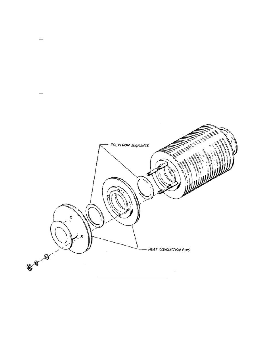
spurious modes. As shown in figure 93, the mode filter comprises a series of polyiron segments inserted in the
waveguide wall. These polyiron segments absorb the currents that might be contained in the waveguide wall and
then transmit this energy in the form of heat to the surrounding air through the heat-conducting fins.
b. Mode filters are usually placed near the outputs of mode launchers and near flexible sections of
waveguide. When placed near the mode launcher as shown in figure 92, the filter removes the energy that was
propagated at the TE rectangular mode, which might have passed through the mode launcher from the rectangular
waveguide. When used near a section of flexible waveguide, the filter is used to eliminate any spurious modes
that may have been set up by the bands and ridges of the flexible waveguide section.
Figure 93. Assembly of mode filter.
344 L2
87


 Previous Page
