Learning Event 3:
DEFINE A NOR OR NAND CIRCUIT
1.
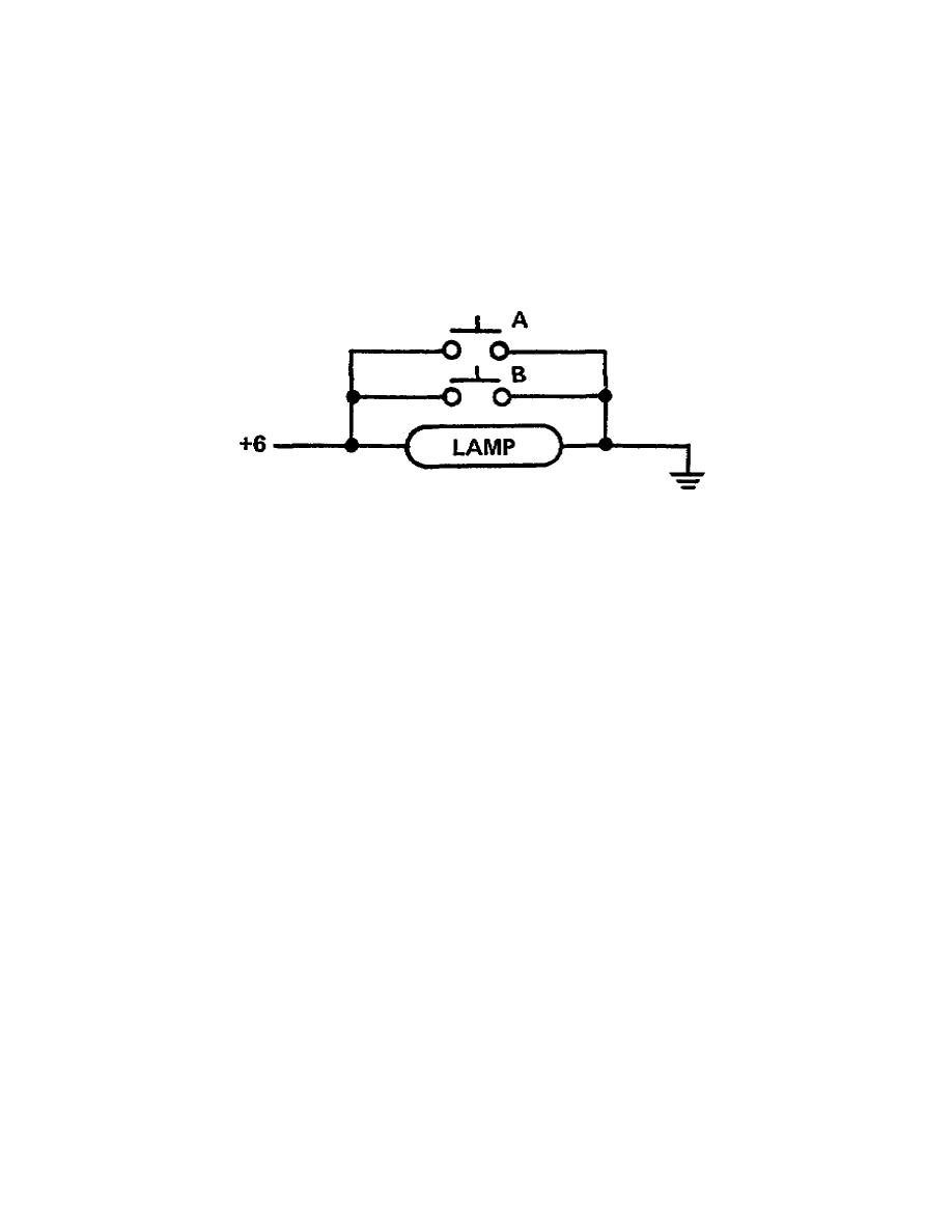
Two switches and a lamp can be arranged as shown in Figure 3-9 to represent the NOR function.
If neither A nor B is closed (on) there is current through the lamp and light as the output. However, if
either or both of the switches is closed (on) the output will be off. A closed switch provides a path of
lower resistance than the lamp, so the current flows around the lamp. For this arrangement, there would
have to be a resistor between the power supply and the input point (labeled +6) to prevent a short to
ground when a switch is closed.
Figure 3-9. Two switches as a NOR gate
2.
The transistorized NOR circuit shown in A, Figure 3-10, is less complicated than either the
transistorized AND or OR gate. Only one transistor is required for the NOR circuit. We don't need two
transistors because a NOR is just an OR with an inverter (NOT OR). The diodes (CR1, CR2) and
resistor form a simple OR gate and Q1 is the inverter-amplifier.
a. When either input is a high, or both are high, the associated diode(s) is forward biased and
the positive potential is coupled to the base of Q1. Q1 conducts and the output is a low. The three
possible conditions of high inputs are lines 2, 3, and 4 of the truth table in B, Figure 3-10. Only when
the inputs are both lows will the circuit provide a high output (line 1 of the truth table). A low on input
A and a low on input B reverse biases both diodes and a low is established on the base of Q1. A low
causes Q1 to cut off and the output is a high. The binary expression for this circuit would be: a 1 output
if neither A NOR B is 1.
b. Notice that we get amplification or signal restoration from the NOR gate. For example, if the
binary 1 inputs to this circuit have degenerated to +3 volts, the output will be corrected to +6 volts.
(You can see now that the transistor Q2 in the OR circuit schematic (fig 3-3) is needed only to reinvert
the output of Q1. Without it, the circuit is a NOR gate.)
26


 Previous Page
