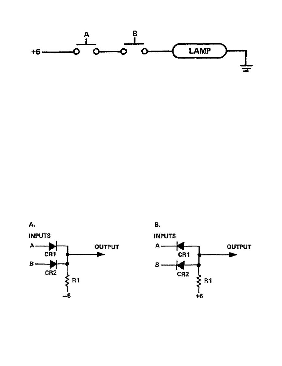
Figure 3-5. Two switch as an AND gate
b. Only if switch A AND switch B are closed is there an output - light.
c. Only with both switches closed will there be current from ground, through the bulb, to the
voltage source.
2.
If we call the switches "inputs" and consider them "on" when they are closed, then the circuit
follows the rules we use to identify AND gates. If all the inputs are on, then the output is on, but if any
input is off, then the output is off. Restated in logic circuit terminology: all is (highs) in, cause a 1
(high) out. With -6 volts instead of +6 the circuit is a negative logic AND gate: all 1s (lows) in cause a
1 (low) out.
3.
A simple diode AND gate can be constructed with the same parts used for the OR gate - two
diodes and a resistor. For example, compare the circuits in Figure 3-6 with the circuits in Figure 3-2.
They are the same with one exception; resistor R1 is connected to -6 or +6 volts instead of ground.
a. The following are the four possible conditions that can appear at the input to the diode AND
gate. We'll apply the conditions to a positive logic AND gate (B, Figure 3-6) with the voltage levels +6
volts as a high, or binary 1; and, 0 voltage as a low, or binary 0.
Figure 3-6. Diode AND gate
23


 Previous Page
