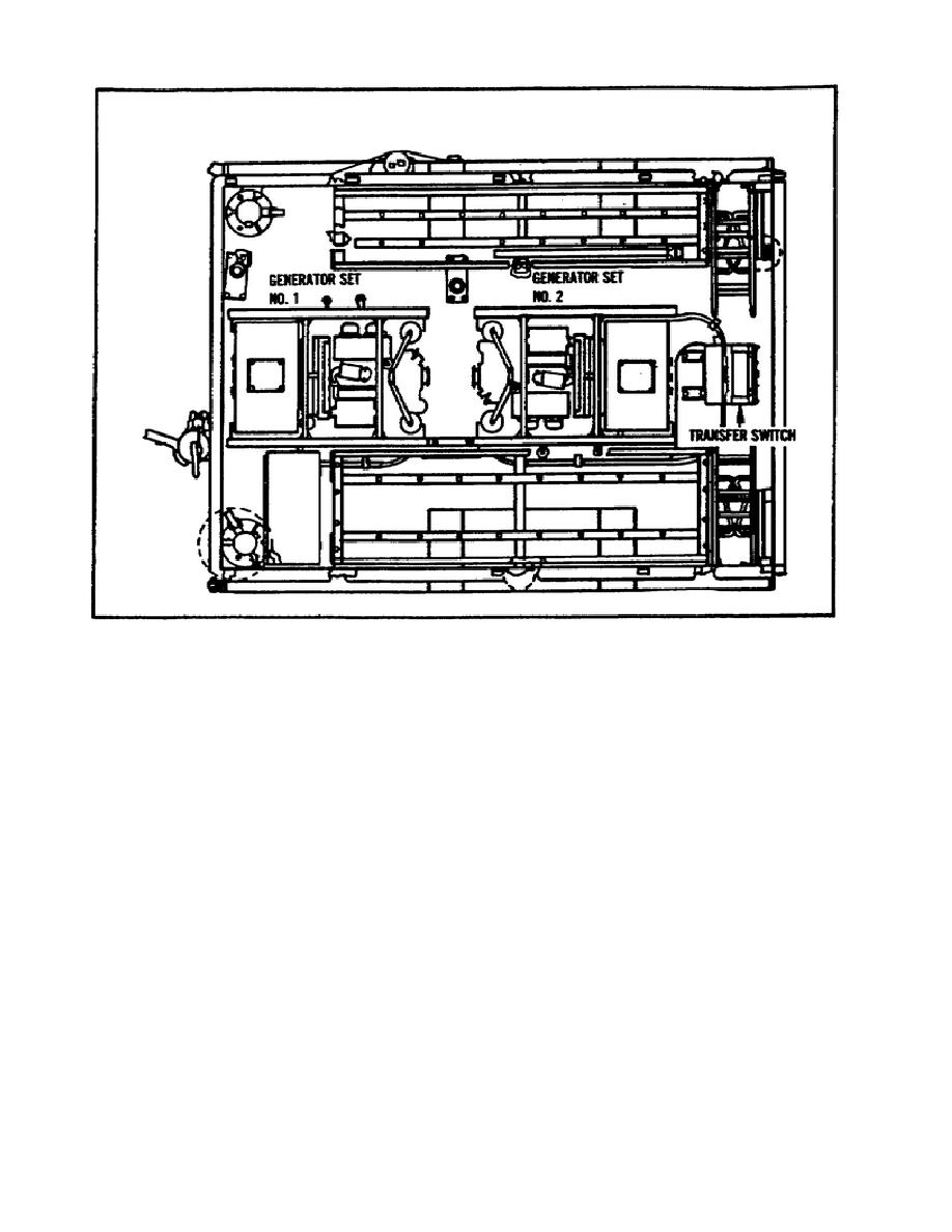
FIGURE 14.
POWER UNIT, PU-625/G (LESS FIXED RACKS).
(2) Refer to paragraph 3f and Figure 11 to start the standby
generator set.
(3) Refer to paragraph 3h and Figure 13 to operate the standby
generator set.
(4) In this case, assume that operating generator set is
generator set number 1, and the standby generator set is generator
set number 2.
(See Figure 14.) Transfer the generator load from
generator set number 2 by positioning the TRANSFER SWITCH knob to the
generator set number 2 position.
j. Stopping. Normal and emergency stopping procedures are given
below. (See Figure 15.)
(1) Place circuit breaker in OFF Position.
(2) Turn VARIABLE RESISTOR knob
(labeled
ADJUST
VOLTS
and
INCREASE VOLTS) fully counterclockwise.
(3) Place GOVERNOR control in START AND IDLE position and allow
engine to idle for three to five minutes.
19


 Previous Page
