(4) Position
GOVERNOR
control
in
START
position.
(See Figure 30.)
(5) Position
REMOTE-LOCAL
switch
in
LOCAL
position.
(See
Figure 31.)
(6) Position
RUN-STOP
switch
in
EMER
RUN
position.
(See Figure 31.)
(7) Position CHOKE control 3/4 closed.
(See Figure 32.)
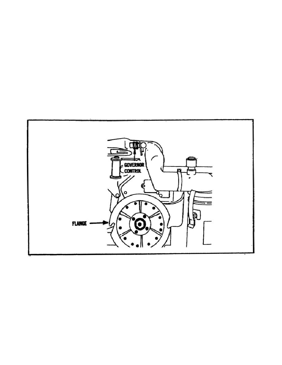
(8) Wrap the starter rope on flange assemble and take one quick
steady pull. If the engine does not start, close choke all the way,
pull starter rope until engine starts. (See Figure 34.)
FIGURE 34.
FLANGE.
(9) Place START-STOP switch in START position.
Battery amp
meter should now indicate on plus side of scale.
(10) Place EMER-RUN-STOP switch in NORMAL position.
(11) Adjust CHOKE control, as necessary, as engine warms up.
50


 Previous Page
