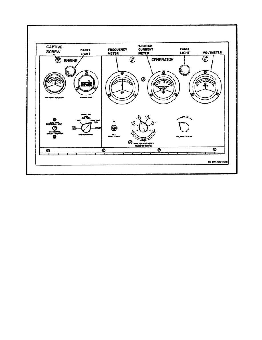
FIGURE 45.
CONTROL PANEL.
d. Ensure MASTER switch returns to PRIME and RUN position when
released.
If running from auxiliary fuel source, move MASTER switch
to PRIME and RUN AUX FUEL position (See Figure 45.)
e. After warm up, check oil gauge indication of at least 20 psi
minimum.
f. Check frequency meter for an indication of 60 Hz.
If
adjustment is required, pull the SPEED CONTROL knob out to increase
and push in to decrease. (See Figure 45.)
g. Place
TRANSFER
switch
in
position
corresponding to the position of the RECONNECTION switch.
Adjust
voltage adjust rheostat to desired voltage as read on voltmeter.
Turn rheostat clockwise to increase voltage or counterclockwise to
decrease voltage.
72


 Previous Page
