(1) Remove the 12 mounting nuts and move the board until the
arrow at its edge match with arrow on the stationary board indicating
the desired operation voltage.
Ensure that mounting nuts are
securely tightened. (See Figure 52.)
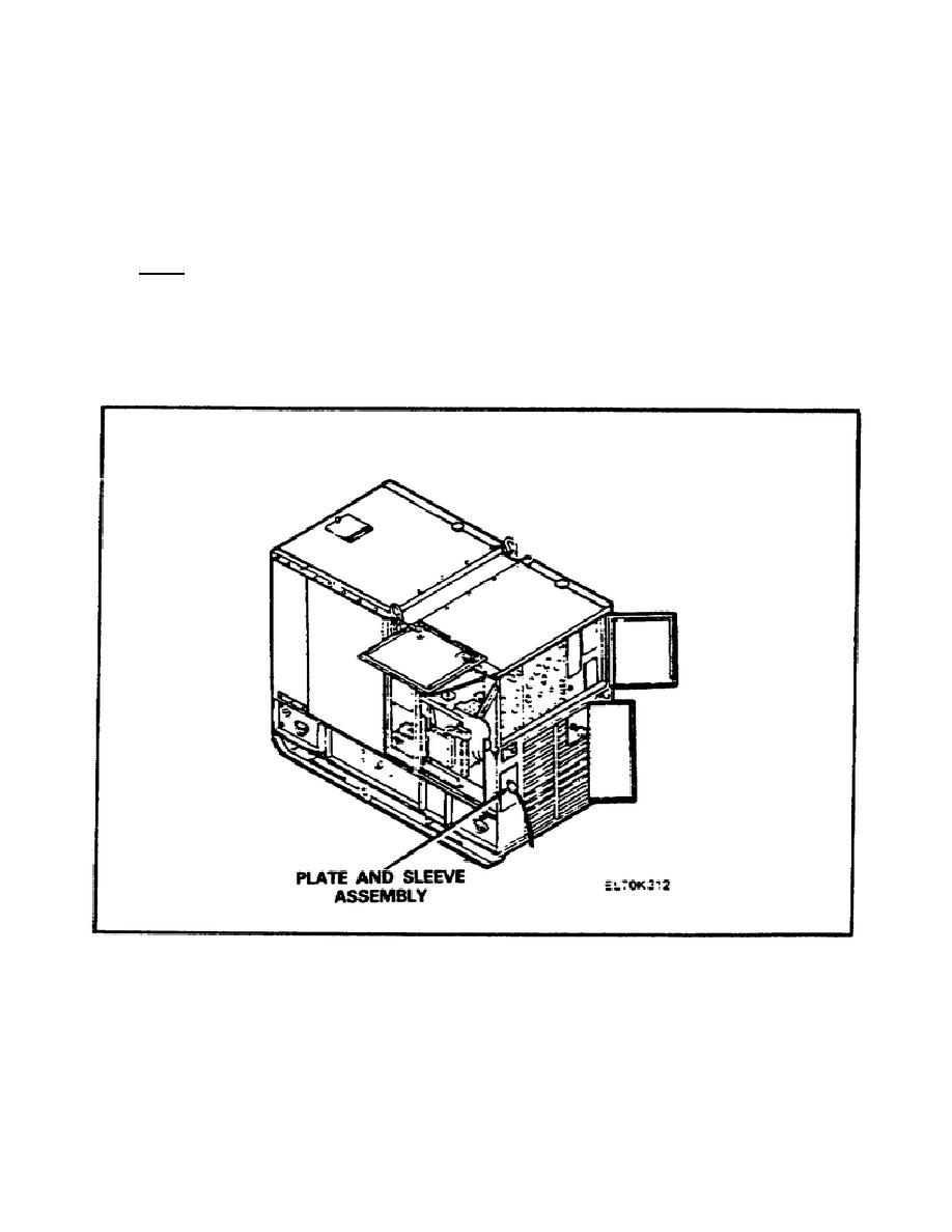
(2) Route all lead ends of the cable through plate and sleeve
assembly (Figure 52) and into load terminal board (Figure 53).
NOTE:
The terminals will accommodate two-wire single-
phase and four-wire three-phase loads. One or
more single-phase loads can be served alone or
in combinations with three-phase loads; but the
load on any one phase must not exceed 100
percent of the current rating of that phase.
FIGURE 52.
PLATE AND SLEEVE ASSEMBLY.
89


 Previous Page
