Lesson 3/Learning Event 5
a. VF Circuits. All VF circuits (2W, 4W, and trunks) pass through the
cable patch bays (1, 2, and 3) for flexibility and convenience in testing.
Conversion between 2W and 4W is made in bay 13, as needed.
Ringers,
converters, and pulse-link repeaters are applied as required.
All
circuits pass through the equal-level patch bays (4 and 5), and all
routine circuit patching is performed at these bays. All circuits passing
through equal-level patch bays are 4W only; 2W circuits must first be
converted to 4W and then restored to 2W to pass through these bays.
Attenuators to insert loss are located in bays 1, 2, and 3; amplifiers to
insert gain are located in bays 4 and 5. The interrelationship of these
cabinets is shown in figure 3-10.
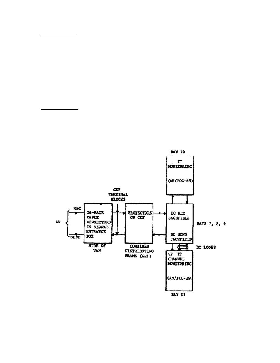
b. DC Circuits.
All DC circuits pass through their respective send
and receive jackfields in bays 7, 8, and 9, Teletypewriter circuits are
monitored by Teletypewriter Set AN/FGC-69 in bay 10.
Channel monitoring
of VF telegraph terminal circuits is accomplished by Telegraph Terminal
AN/FCC-19 in bay 11. The interrelationship of these cabinets is shown in
figure 3-11.
Figure 3-11.
DC Circuits in the AN/MSQ-73, Block Diagram.
90


 Previous Page
