Lesson 3/Learning Event 5
(2) Printed circuit wiring (dotted lines) on the back of the card
connects to the resistors.
Resistors on the front of the card are
strapped into and out of the circuit by soldering short jumper wires.
(3) Loss can be varied from 0 to 31.5 dB in 0.5-dB steps by selecting
the correct combination of pads. The attenuator shown in figure 3-12 has
14-dB loss, the sum of 8, 4, and 2 dB. The 16-, 1.0-, and 0.5-dB pads are
strapped out of the circuit.
f. VF Jack Arrangements.
Almost all VF jacks in the AN/MSQ-73 are
normal-through; that is, with no plug in a jack the leaf contacts of the
jack complete the circuit.
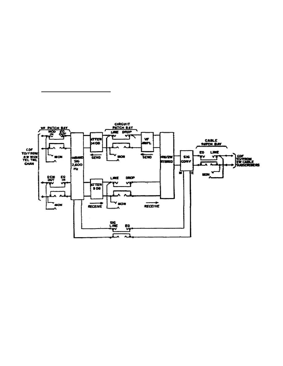
An example of the jack arrangements in a 2W
2,600-Hz ringdown telephone circuit is shown in figure 3-13.
Figure 3-13.
Circuit Arrangement of a Telephone Channel.
(1) Whenever a plug is patched into a jack, the normal-through contacts
are broken and the circuit is picked up on the tip and ring of the plug.
(2) A plug "looks" in the direction it is patched. For example, if the
plug is patched into the DROP jack of the circuit patch bay, it "looks"
back toward the VF amplifier and breaks the circuit to the 14-dB
attenuator.
93


 Previous Page
