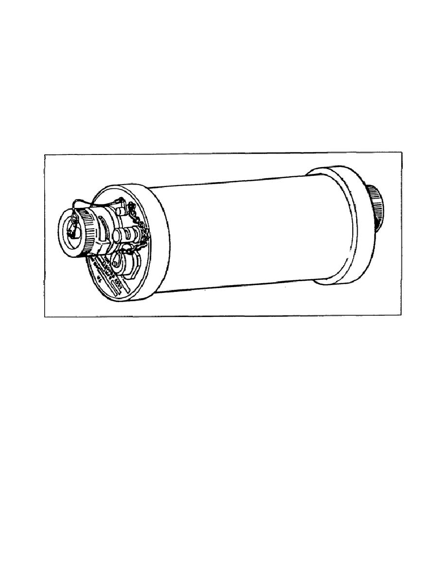
d. Built-in test connector for connection of the COU.
e. Used with the AN/TRC-175, AN/TRC-138A, and AN/TSQ-111.
f.
Handles information at 19,200 kb/s.
g. Amplifies a 30 millivolt peak-to-peak signal to 1.5 volts peak-to-
peak.
h. Requires 2 watts, 90 milliamps constant current supplied from the
MD-10244/G at both ends of the cable line.
Figure 2-8.
Pulse form restorer TD-1219/G.
48. Now you are asking yourself why were these pieces of equipment placed
at this point in the lesson. During the construction phase, you will have
to install one or more of the items listed above. When you do install them,
you must provide for their protection. After all, they are about the size
of a football and probably weigh about the same. They are delicate because
of the printed circuit boards inside so they cannot be handled roughly.
These items should be well off the road for protection.
49. When it is time for you to install a restorer, as they are sometimes
called, you need to make a cradle for it. You will need four stakes. Drive
them into the ground so they make an X and wide enough apart so that you can
place the restorer on the stakes and have the ends protruding.
You must
remember to provide about 18" to 24" of loose cable to connect to the
restorer.
You do not want any strain on the connector ends, so you will
also have to prepare a tension loop as described earlier. Do not forget to
tag the cable at approximately 6" from the connection to the restorer. See
Figure 2-9 on page 2-14.
2-13
SS0444


 Previous Page
