e. Test procedure 9.
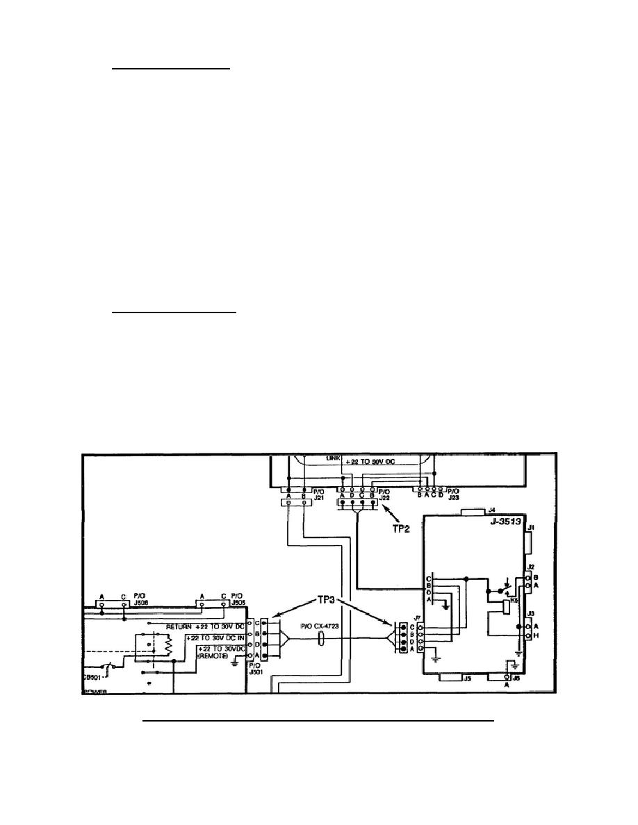
The next test point is the MT-1029 J22 pins A and
B (TP2) (Figure 30).
To get to J22, disconnect the cabling to the RT, remove the RT,
disassemble the MT-1029, and remove P1 from J22.
Measure the voltage at TP2.
If there is no voltage at TP2, the MT-1029 is the bad item.
Repair if possible, if not send to IDS for repair.
If there is 22-30 volts at J22 pins A and B, the MT-1029 is not
the bad item.
The J-3513 and CX-4723 are the last two items to check. The J-
3513 is not checked due to the level of difficulty of making
checks on the J-3513.
f. Test procedure 10.
The next check, TP3, will measure continuity of the CX-4723 pin B
to pin B.
If no continuity is measured, the CX-4723 is bad and will be
replaced.
If continuity is measured, the J-3513 is bad.
Turn in to the
COMSEC support maintenance for repair (Figure 30).
Figure 30.
DC power, TP2 and TP3 (22-30 volts DC).
32


 Previous Page
