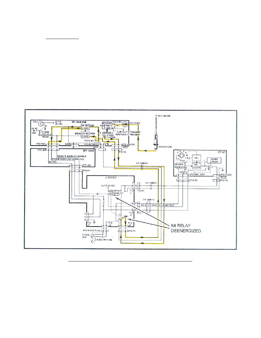
18. MONITORING CIRCUIT.
a. Plain text.
The RF signal received at the antenna is applied
through the antenna system AS-1729/VRC, through the CG-1773/U to the RT, RF
connector (Figure 57). The RF signal is applied to the RF and IF assemblies
and demodulated to an AF signal.
The AF signal is applied through the X
MODE switch of the IF A4000 assembly (when set to X MODE) and to pin A of
the X MODE jack of the RT. The AF signal is applied from the RT, through
the CX-13064/U to the J-3513/U J6 pin P, through the K8B relay (KY-57 is
OFF) back to J6 pin K, back through the CX-13064/U pin C of the RT X MODE
jack.
Then the AF signal is applied to the SQUELCH SECTION.
The audio
signal in the squelch section is divided into three outputs: The Speaker Out
(not shown on figure), the Muted Out, and the Unmuted Out. The outputs are
applied to J24 of the MT-1029, pin K Muted and pin S Unmuted. (Trace these
circuits on your system diagram.)
Figure 57.
Monitoring circuit (plain text).
65


 Previous Page
