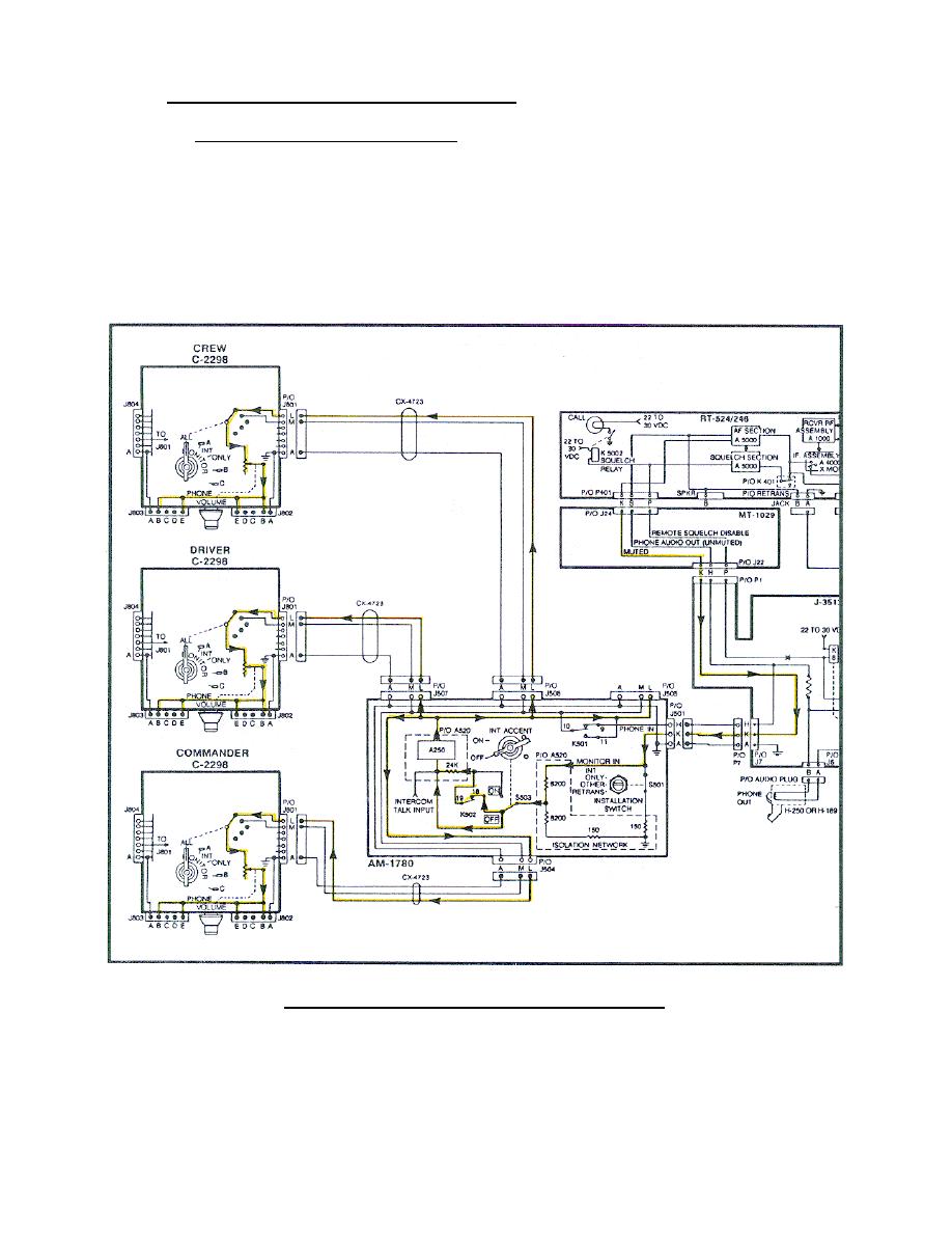
c. Muted/unmuted monitoring circuits.
(1) Muted monitoring circuit. The muted signal is applied from the
RT to the MT-1029 J24 pin K (through the MT-1029, J3513, CX-4723) to the AM-
1780 J501 pin K (Figure 59). The signal is applied through the isolation
network and S503 switch to the A250; where it is amplified and applied to
J504, J505, J506, and J507, pins L; through the CX-4723 to the C-2298. In
the C-2298 the muted signal is applied from J801 pin L, through the monitor
switch (set at ALL), through the volume control resistor.
It is then
applied to pins B and E of J802 and J803, then to the audio accessory.
(Trace this circuit on your system diagram.)
Figure 59.
Muted monitoring circuit.
68


 Previous Page
