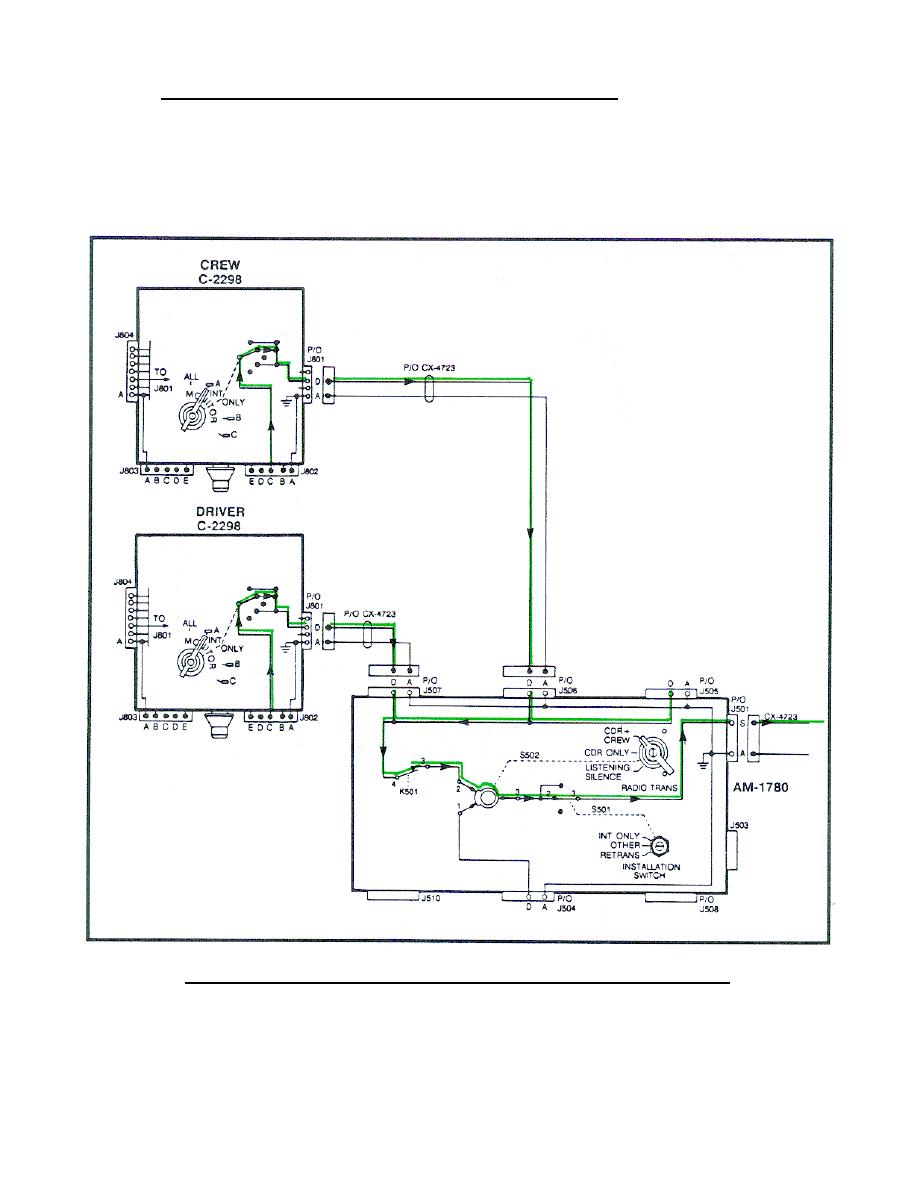
b. Crew member's/driver's A-RT keying circuits.
The crew member's/
driver's keying circuit starts at the C-2298 J802 pin C (Figure 63) and is
applied through the MONITOR switch (when set to ALL, A, or B) to pin D J801,
through the CX-4723 to the AM-1780 J505, J506, J507 pin D. In the AM-1780
the circuit is applied through pin 2 to pin 3 S502 (when set to CDR + CREW),
through switch S501 (when set to OTHER) to J501 pin S, through the CX-4723.
(Trace these circuits on your system diagram.)
Figure 63.
Crew member's/driver's A-RT keying circuit.
72


 Previous Page
