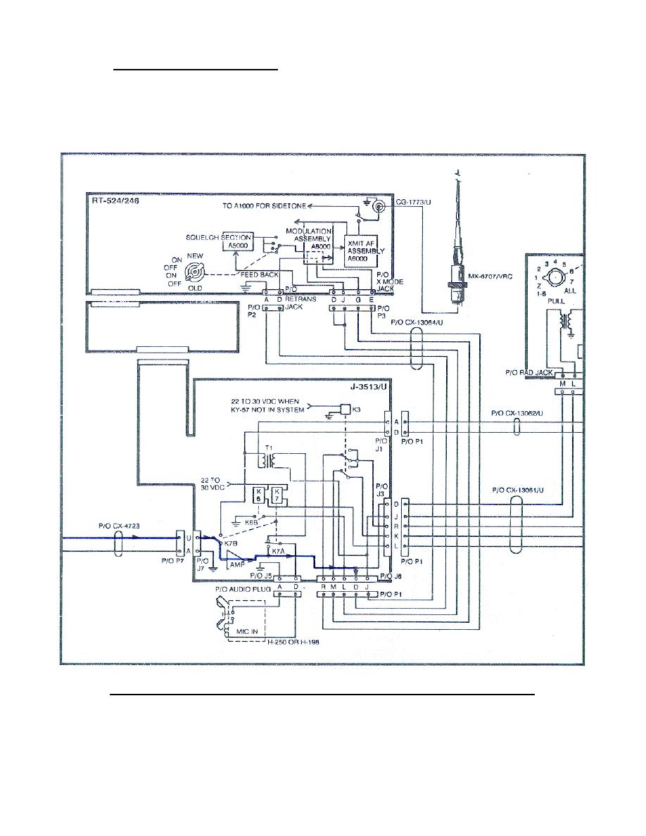
b. Signal within J-3513/U.
In the J-3513/U J7 pin U the signal from
the AN/VIC-1 is applied (through the K7B and Amp) to pin D J6 (Figure 66).
The audio signal from a handset at J5 is applied to pin D (through K7A) to
pin D of J6 (when used). (Trace these circuits on your system diagram.)
NOTE:
Relays K3, K6, and K7 are deenergized in plain text operation.
Figure 66.
Modulation circuit KY-57 turned OFF (plain text).
75


 Previous Page
